ADBnox USB User Guide
ADBnox USB turns your Android phone into a USB workstation. It prepares Windows and Linux installation drives, formats and partitions USB drives, tests their health and real capacity, and programs Arduino, ESP and Raspberry Pi Pico boards. No root, ADB or computer needed.
This guide walks through every screen of the app: what it is for, what you need, how to do it step by step, what you will see, what can go wrong and how to undo it.
00 About this guide and its labels
Button names follow the English interface; in Turkish they are shown in Turkish. The app's own User Guide screen is a short summary of this page.
Labels used in the text
| Label | Meaning |
|---|---|
| VERIFIED | Tried end to end on a real phone and drive. |
| EXPERIMENTAL | Works and passes automated tests or a virtual machine, but has not yet been tried end to end on real hardware. Make a backup before using it for anything important. |
| ROOT | Works only on rooted phones. |
| PC | Part of the job is done on a computer (e.g. compiling code). |
The search box at the top right (/ key) shows only the paragraphs that contain every word you type and hides the rest.
How well has each feature been tested?
ADBnox USB is developing fast. The table below honestly shows how each feature has been tested as of version 1.0.1.
| Feature | Status | How it was tested |
|---|---|---|
| Formatting a USB drive as FAT32 / exFAT | VERIFIED | Real phone + USB 3.2 drive |
| Writing disk images (.img/.gz/.xz) and hybrid ISOs | VERIFIED | Real phone, SHA-256 read-back |
| Windows installation drive (file copy, split WIM) | EXPERIMENTAL | Unit tests and comparison with WIM tools; a real installation has not been tried yet |
| Windows Setup options (autounattend.xml) | EXPERIMENTAL | The generated file was checked against the schema; not tried in a real installation |
| ADBnox MultiBoot | EXPERIMENTAL | ISO menu and booting in a UEFI virtual machine |
| Network boot (iPXE, HTTP server) | EXPERIMENTAL | iPXE in a virtual machine with a stand-in for the phone's server; booting Linux ISOs over the network is not verified yet |
| Fake-capacity test, speed test, surface scan | EXPERIMENTAL | Unit tests on a simulated fake drive (address wrap-around) |
| Arduino / ESP / DFU / UF2 programming | EXPERIMENTAL | Protocol tests; IoT Agent for Uno in an emulator (simavr). On a phone with a NodeMCU (CH340): the board entered download mode, but up to 0.12.21 no connection was made. The logs showed that the app lost data while reading from USB; the ESP8266's 96-byte connection answer is exactly three CH340 packets and may have been lost on every attempt. 0.13.0 fixes this reading error; it has not been retried on a real board yet. |
| IoT Agent Wi-Fi web panel | EXPERIMENTAL | Panel tested in a browser against a server that imitates the board |
| IoT Agent automation rules, soil moisture calibration | EXPERIMENTAL | Uno firmware in an emulator (simavr): threshold, time limit, save/load; unit tests of the rule logic |
| MQTT and Home Assistant | EXPERIMENTAL | MQTT client tested on a computer against a real MQTT server; not yet tried on an ESP board or in Home Assistant |
| IoT Agent wireless update (signed package) | EXPERIMENTAL | Signature check unit-tested on a computer; update and rollback tested over the serial line in the ESP32-C3 emulator (QEMU): damaged, foreign-signed, wrong-board and older packages were refused; a good version installed and confirmed itself; with a version that crashes at start the board returned to the previous agent. Not yet tried on a real board or over Wi-Fi |
| Compile on the server and flash | EXPERIMENTAL | The server compiler was tested for every board with the real toolchain; compiling from the phone and flashing a real board not yet tried |
| RF Remote Cloner & Transmitter (NodeMCU / ESP8266, ESP32, Uno) | EXPERIMENTAL | All generated C++ sketches and pre-compiled firmwares across 5 RF module families and 6 examples were verified on the AVR, ESP8266, ESP32 and RP2040 compilers; not yet field-tested with a physical RF remote The 1.5.3 decoder and sender were round-trip tested with the real C++ code against a simulated receiver that stretches pulses by 0–160 µs (pulse length within ±4%); no measurement with a real module yet. |
| ADBnox IoT Agent RF / IR remote library, hold to repeat | EXPERIMENTAL | The Agent's RF code was tested in simulation (EV1527 codes, a stretching receiver, rejection of 2:1 and 28-bit frames, hearing its own transmission); the library, hold to repeat and file backup with app tests. Not yet tried with a real module and remote. |
| Samsung Odin (Download Mode) | EXPERIMENTAL | Protocol written from Heimdall's source code; tested against a simulated device that really decodes the packets and rebuilds the partition. On the first try on a real Galaxy tablet the write stopped halfway: when the device was slow to answer while writing the previous sequence, the engine did not wait and ask again. 0.12.7 retries as Heimdall does, but has not been tried on a real device again. Make the first try with an unimportant partition (e.g. recovery); if a write stops halfway, recover the device on a computer with Odin and the official firmware. |
| Android Fastboot / Fastbootd | EXPERIMENTAL | Written to behave like AOSP fastboot; sparse splitting, A/B slots and the lock check were tested with a simulated device. Not yet tried on a real phone: make the first try on the unused slot. |
| IoT Agent Bluetooth (ESP32, S3, C3) | EXPERIMENTAL | Board firmware and app compile; pairing and connecting not yet tried on a real board and phone (the emulator has no Bluetooth) |
| SCD40, PZEM-004T, VL53L0X, WS2812, OLED, LCD drivers | EXPERIMENTAL | Written from the datasheets and compiled for every board; not yet tried with a real sensor |
| Virtual drive (showing the phone as a USB drive) | ROOT | Rooted phones only |
If you tell us how a feature worked for you (worked / did not work, phone and drive model), we will update this table.
01 Getting started
What you need, how to connect a drive or board, and how to grant permission.
Requirements
- Phone or tablet: Android 8.0 or later with USB Host (OTG) support. Almost every current phone supports OTG.
- OTG adapter: a USB-C → USB-A adapter (or Micro-USB → USB-A on older phones). Drives with a USB-C plug need no adapter.
- Power: USB drives, SD card readers and Arduino boards run on the phone's power. For 2.5″ external disks and SSDs, use an OTG hub with external power.
- Root, ADB, Shizuku: not needed. The app talks to the drive directly through Android's standard USB Host interface.
If nothing happens when you plug in a drive, turn on the phone's Settings → Additional settings → OTG option (the name depends on the brand and version). Some phones turn this setting off by themselves after a few minutes of inactivity.
First connection and USB permission
- Open ADBnox USB, then plug in the drive or board with OTG.
- The app opens the “Allow ADBnox USB to access this device?” dialog by itself. Tap OK. If you tick “Open by default for this USB device”, you will not be asked the next time.
- If you missed the dialog, tap Grant USB Permission next to the device on the Devices screen.
- The OTG Active badge in the top bar shows that a device is connected. The drive's name and capacity appear as a target on the Flash Image, Disk & Format and Tools & Tests screens.
Screens
The tab bar under the logo, which scrolls sideways, leads to these screens:
Devices screen
Every connected USB device appears here as a card: manufacturer and product name, VID:PID identity, USB class (mass storage, CDC serial, HID…), serial number and permission state.
- USB Hardware & Descriptor Inspector: shows the device's configurations, interfaces, endpoints and the current it draws (mA). Share Report copies it as text.
- Feasibility Probe: runs read-only tests: INQUIRY, TEST UNIT READY, READ CAPACITY, a few sector reads and SYNCHRONIZE CACHE. The result can be exported as JSON. If a drive misbehaves, send this report when asking for support.
- Write test: after the scan you can optionally write one sector and read it back. Use it only on a drive you can afford to lose; if the connection drops during the test, that sector may stay changed.
Write operations are bound to the drive's identity (see Safety model). Cheap drives that report no serial number have a weak identity. The app says so on the card and checks the identity more strictly.
Long operations, background and the floating panel
- Writing, formatting and disk operations run in an Android foreground service. The job continues even if you leave the app; the notification shows progress and a Cancel button.
- With Settings → Keep Screen On During Operations on, the screen stays on while a job runs. Some phones cut USB power when the screen turns off; keep this setting on for long writes.
- Floating panel (PiP): if you switch to another app during a job, a small progress window appears. It is turned on and off in Settings, where you also choose its aspect ratio (16:9, 4:3, 21:9).
- While one job is running, a second USB job cannot start. The app warns that “another operation is using the USB device”.
02 Safety model: how your data is protected
Because the phone can write to a drive sector by sector, erasing the wrong drive is easy. ADBnox USB prevents this with several layers.
Identity-bound confirmation
- Before any operation that erases data, a full-screen confirmation is shown: the drive's name, VID:PID identity, serial number, capacity and a list of what will happen (e.g. “The image will overwrite the drive starting at sector 0”).
- The confirmation is bound to that drive's identity. Just before writing starts, the identity is read again. If the drive was removed and another one plugged in meanwhile, the operation does not start (“Hardware identity verification failed”).
- With Settings → Destructive Action Guard (Strict Guard) on, this check is required for every format and write. We recommend leaving it on.
What does “Verified” mean?
When writing finishes, the app reads the written data back from the drive and compares its SHA-256 digest with the source. If the digests match, the data on the drive is an exact copy of the source. The verification modes are described in the Flash Image chapter.
What can and cannot be undone?
| Operation | Can it be undone? |
|---|---|
| Partition table changes (active, hide, type, move to slot 1) | Yes. First make a backup with Backup Partition Table (.adbnxbr); the backup can be restored to the same drive. |
| Loading MBR boot code | Yes, with the same backup. |
| Changing sector bytes (hex) | Yes. Save the sector as .bin first. |
| Formatting, repartitioning, writing an image | No. Old files are deleted. Make a disk image backup first. |
| Sector fill (zero / random) | No. |
| Fake-capacity “boundary write test” | The test backs up the sectors and writes them back; if the drive really is fake, restoring may fail. |
The controller in USB drives and SD cards spreads written data over different physical cells. Even writing zeros over every sector does not guarantee that every copy of the old data is gone. Physically destroy a drive that held secret data before you throw it away.
03 Flash Image: writing ISO and disk images
Writes an operating system image or a disk backup to a USB drive or SD card. The app recognises the file type by itself and chooses the best method.
Supported files
.iso: Windows, Linux and rescue ISOs..img,.bin: raw disk images (Raspberry Pi OS, Armbian, router firmware, drive backups made earlier)..img.gz,.img.xz,.gz,.xz: compressed images. You do not need to unpack them first; they are unpacked while writing and take no extra space on the phone.
The “image type” step: what will the app do?
When you choose a file, the app inspects it and shows one of these types:
| Shown on screen | Meaning | How it is written |
|---|---|---|
| Disk image | The partition table and file system are inside the image. | As-is, from sector 0. |
| Hybrid ISO | An ISO with an MBR/GPT at the start. Most Linux distributions are like this. | As-is; the drive boots from USB. |
| Windows installation ISO | No partition table; it would not boot if written as-is. | The drive is partitioned with GPT or MBR, formatted FAT32 and the ISO's files are copied. See chapter 4. |
| UEFI-bootable ISO without a partition table | Some rescue ISOs. | FAT32 + file copy. |
| Standard BIOS / El Torito ISO | Old ISOs that only boot like a CD. | Written raw (sector by sector); booting from USB is not guaranteed. |
If the ISO contains a file that does not fit on FAT32 (4 GiB or more), it is shown by name. In that case Windows's install.wim is split into parts automatically (see split WIM).
Writing step by step
- On the Flash Image screen tap Select Image (.ISO / .IMG) and choose the file. It can be on the phone, on an SD card or in cloud folders shown by Android's file picker. Files you downloaded from the app's rescue library also appear in the Downloads list.
- The app inspects the file and shows its type. If you have an official SHA-256 digest, paste it into the Expected SHA-256 Checksum field; the file is compared with it before writing.
- Choose the target drive. If several drives are connected, check the name and capacity.
- Choose the verification mode (see below).
- Tap WRITE TO USB (START). Read the planned operations in the confirmation dialog and confirm.
- The progress screen shows the current speed, remaining time and stage. When the job ends, the result and verification report are shown and an entry is added to History.
Verification modes
| Mode | What it does | When |
|---|---|---|
| Full Verification (recommended) | Reads back every written byte and compares it with SHA-256. | Always, especially for installation drives. |
| Sampled Verification | Checks the first, last and 30 random blocks. | A quick check for very large images. |
| Verification Disabled | No read-back. | Not recommended. |
If verification ends with this error, the drive is either faulty or has a fake capacity. Run the fake-capacity test; if it is fake, do not use the drive.
Cancelling
Tap Cancel on the progress screen or in the notification. A half-written drive will not boot; write it again or format it.
Write speed
- Speed depends on the drive, the phone's USB port (USB 2.0 / 3.x) and the adapter. A USB 3 drive, a USB 3 phone and a USB 3 adapter together give the best result.
- Many fast drives slow down after the first few GB because their internal cache fills up. This is normal; writing continues even if it looks stalled.
- Settings → USB Transfer Buffer Size: a large buffer increases speed on USB 3 drives. Make it smaller if the connection drops.
04 Windows installation drive EXPERIMENTAL
From a Windows 10 or 11 ISO, prepares an installation drive that boots on UEFI computers (also with Secure Boot on). If you like, it answers the questions Windows Setup asks in advance.
Getting the original ISO
- Download the ISO only from Microsoft's official “Download Windows 11” / “Download Windows 10” page. In the phone's browser the page offers the ISO option directly.
- The page gives a SHA-256 value next to the download. Paste it into the “Expected SHA-256” field on Flash Image; the app checks that the file is neither damaged nor modified.
ADBnox USB does not touch activation or licensing. You activate Windows with your own product key or the computer's digital licence.
Partition scheme: GPT or MBR?
- GPT (recommended): the standard choice for UEFI computers.
- MBR: for some UEFI firmware that does not recognise GPT on a USB drive. The partition is FAT32 (type 0x0C) and marked active.
With either option the drive boots with UEFI, even with Secure Boot on. It does not boot only on computers that use old BIOS/Legacy (roughly before 2012).
FAT32 and split WIM
UEFI firmware can always read FAT32, but most cannot read NTFS. On FAT32, however, a file can be at most 4 GiB, while install.wim in new Windows ISOs is often larger. ADBnox USB splits this file into install.swm, install2.swm… parts. Windows Setup joins the parts by itself. So the drive boots with Secure Boot on and no NTFS driver is needed.
If an install.esd file is larger than 4 GiB, it cannot be split and the app rejects the ISO. In that case download the current ISO from Microsoft's page.
Edition list
When an ISO is chosen, the editions inside it (Home, Pro, Education…) and the build number are listed. The list is for information; which edition is installed is decided by the edition choice setting below or on Setup's own screen.
Windows Setup options
When a Windows ISO is chosen, the Windows Setup options panel opens. All of them are off by default. The options you turn on are written to the root of the drive as an autounattend.xml answer file; Windows Setup reads it by itself. This file is verified like all the other files.
Remove the TPM 2.0, Secure Boot and 4 GB RAM requirement
Skips Windows 11 Setup's hardware checks (LabConfig registry values in the Setup environment: BypassTPMCheck, BypassSecureBootCheck, BypassRAMCheck). Offered for Windows 11 ISOs and ISOs whose version cannot be recognised.
Windows 11 24H2 and later checks whether the processor supports the POPCNT / SSE4.2 instructions. This is not a software check but a property of the processor itself; no setting can get around it. On very old processors Windows will not run even if Setup starts.
Remove the Microsoft account requirement
Lets Setup finish without internet and without a Microsoft account (BypassNRO, hiding the online account pages). Microsoft makes this harder in newer releases. The most reliable way is to use this option together with a local account.
If Setup still asks for an account, unplug the computer's network cable or do not connect to Wi-Fi. Without a network, Setup continues with a local account.
Create a local account
Creates a local account with administrator rights and the name you type. The password is empty and Windows asks for a new password at the second sign-in; no password is written to the drive. The password does not expire. The name is checked against Windows's rules (at most 20 characters, no \ / [ ] : ; | = , + * ? < > ").
Use this phone's regional settings
The phone's language and time zone set Windows's input language, system locale, user locale and time zone. On a Turkish phone, for example, the Turkish Q keyboard and “Turkey Standard Time” are chosen. Windows's display language does not change; that is the ISO's language.
Skip the privacy questions
Hides the “location, diagnostic data, advertising ID…” questions asked at the end of Setup; optional data sharing is set to off (ProtectYourPC = 3).
Turn off automatic BitLocker encryption
On many computers Windows 11 encrypts the disk without asking. The recovery key is saved to the Microsoft account; with a local-account installation this key can be lost. This option prevents automatic encryption. You can turn BitLocker on yourself later.
Driver packs and assistants
- Wi-Fi drivers: the Windows ISO may lack drivers for the Wi-Fi cards of new laptops (MediaTek MT7921/7922, Realtek RTL8852, Intel AX/BE), and Setup gets stuck on the network screen. This option adds a Wi-Fi guide, a driver installer and a script that installs the driver after Setup. You download the driver files (
.inf,.sys,.cat) from the manufacturer's site yourself and add them in the Driver Packages panel. - Intel VMD / RST storage: on 11th–14th generation Intel laptops the NVMe disk sits behind the VMD controller. Setup says “No drives were found”. This option prepares a guide and a
$WinPEDriver$\Storagefolder. You add the manufacturer's “F6” driver package; Setup loads the drivers in this folder by itself. If it does not, point Setup to this folder with Load driver → Browse. - Intel / AMD / NVIDIA graphics assistant: detects the graphics card at first start. If the drive contains a matching package, it installs it; otherwise it opens the manufacturer's official driver page.
Drivers are the manufacturers' copyrighted files and cannot be distributed with the app. ADBnox USB shows the official download pages and places the package you download in the right folder.
Disable Copilot, OneDrive & telemetry
Turns off Windows Copilot, automatic OneDrive sync, ad suggestions in Start, search box suggestions, and News and Interests. Reduces diagnostic data to the minimum. These are policy registry values and can be turned back on later.
Product key, edition choice and computer name
- Product key: if you enter your own key, Setup uses it without asking (
sources\PID.txt). - Edition choice / “Show all editions”: on laptops that came with Windows Home, the key is embedded in the motherboard firmware. That is why Setup installs Home without asking. If “Show all editions” is chosen,
sources\EI.cfgis written to the drive and Setup shows the edition list. You can also choose a specific edition (e.g. Professional). - Computer name: 1–15 characters: letters, digits and hyphens.
Apps after installation
The apps you choose (browser, archiver, office suite…) are installed automatically with Windows's package manager winget at the first sign-in. The script waits until winget is ready; an internet connection is needed.
The “Windows To Go (portable)” flag
Adds the “portable system” registry values (PortableOperatingSystem, SanPolicy = 4) to the installed Windows. This option does not turn the drive itself into a running Windows. Windows Setup usually refuses to install to a USB disk. It is useful if you can install to an external SSD; otherwise leave it off.
Why is there no silent (fully automatic) installation?
An installation drive that erases a disk without asking causes data loss when it is plugged into the wrong computer. That is why choosing the disk is always left to you on Setup's screen.
Troubleshooting
The computer does not boot from the drive
- Open the boot menu (F12, F11, F9 or Esc depending on the brand) and choose the drive's entry that starts with UEFI:.
- If the boot mode in the BIOS settings is “Legacy only”, change it to “UEFI” or “UEFI + CSM”.
- If a drive prepared with GPT is not listed, prepare it again with the MBR option.
- Repeat the write with Full Verification; if verification fails, the drive is faulty.
“No drives were found” / the disk list is empty
This is a laptop with an Intel VMD/RST controller. Prepare the drive with the Intel VMD / RST option, or turn off the VMD Controller setting in the BIOS (if that setting exists and the disk has no RAID).
Stuck on the “Let's connect you to a network” screen
- Open a command prompt with Shift + F10 (Shift + Fn + F10 on laptops).
- Type
OOBE\BYPASSNROand press Enter. The computer restarts. - On the network screen the I don't have internet → Continue with limited setup option appears.
Microsoft removed this command from some new builds. If it does not work, prepare the drive again with the Remove the Microsoft account requirement and local account options.
“We couldn't create a new partition”
Setup may be treating the USB drive as the primary disk. If you get the error after choosing the disk, unplug the drive and tap Refresh, then plug the drive back in and tap Next. If the disk held another operating system before, delete that disk's partitions on the Setup screen and install to the empty space (the data on that disk is deleted).
“The answer file could not be processed”
Very rare; usually caused by an edition name Setup does not know or a wrong product key. Leave the edition/key fields empty and prepare the drive again.
Windows was installed in “S mode”
Some laptops ship with S mode and Setup keeps it. After Windows starts, you can switch out of S mode for free in the Microsoft Store.
Secure Boot revocation (DBX) warning
Microsoft adds old boot loaders to the Secure Boot revocation list. A drive made from a very old ISO may show a “security violation” warning on computers with current firmware. Download a current ISO from Microsoft.
05 Linux, Raspberry Pi and SD cards
Linux installation ISOs and single-board computer images (Raspberry Pi, Orange Pi, ODROID…).
Linux ISOs
ISOs of Ubuntu, Debian, Fedora, Linux Mint, Kali, Arch and similar distributions are hybrid: the app writes them as-is and the drive boots on both UEFI and BIOS computers. Secure Boot support depends on the distribution; Ubuntu, Fedora and Debian also boot with Secure Boot on.
If you do not want to erase the drive every time, copy several ISOs to the same drive with ADBnox MultiBoot and choose one from a menu at boot.
Raspberry Pi and SD card images
- Download the image from the board's official site (Raspberry Pi OS, Armbian, DietPi, Home Assistant OS…). Leave it as
.img.xzor.img.gz; there is no need to unpack it. - Put the microSD card into a USB card reader and connect the reader to the phone. The phone's own SD slot cannot be used: Android does not give apps raw access to that card.
- Without a card, the reader reports “medium not present”; seat the card fully. Check that the capacity is shown correctly.
- On the Flash Image screen choose the image and the reader and write. The app unpacks the image while writing and reads it back with Full Verification.
- Put the card into the Pi. At first boot the system expands the root partition to fill the card.
The “user name, Wi-Fi, SSH” presets in the Pi's official tool are written to first-boot files, not into the image. ADBnox USB writes the image as-is; you make these settings on screen when the Pi first starts.
06 Disk & Format: formatting and low-level disk tools
The tabs at the top of the screen: Printer / TV Doctor, Partition Manager, Repartition, Boot Records (MBR/PBR) and Sectors & Raw Image. First choose the target drive on the card at the top; after a change on the drive, tap Refresh.
Printer, TV and car stereo compatibility
Multifunction printers, televisions, car stereos and satellite receivers only recognise a USB drive that has a single FAT32 partition in slot 1 of an MBR partition table. Drives formatted on Windows or a Mac often carry GPT, exFAT or several partitions, and these devices do not see them.
- Open the Printer / TV Doctor tab. The app checks the drive and lists the problems (GPT, exFAT/NTFS, partition not in slot 1, wrong type code…). If the drive is fine, it says it fully matches the standard layout these devices expect.
- Quick Fix (Preserves Files): fixes only the partition table where possible (e.g. moves the partition to slot 1, changes the type code). Files are not deleted.
- Recommended Fix (Erases Drive): recreates the drive as MBR + a single FAT32 partition. This is the most reliable way; the files on the drive are deleted.
If the device still does not recognise it
Try the alternatives under Appliance Still Not Recognizing? one by one:
- 32 GB limit: limits the FAT32 partition to 32 GB. Some old devices cannot read larger partitions.
- Superfloppy (no partition table): makes the whole drive a single FAT32 volume without a partition table. Some embedded devices read only this.
If a printer does not see a 64 GB drive but sees an 8 GB one, try the Recommended Fix first, then the 32 GB limit. If neither works, the device's firmware looks at the drive's total capacity; no formatting can change that, so use a smaller drive.
Partition Manager
Lists the partitions on the drive with their types, sizes and file systems. It also points out cases such as MBR, GPT, superfloppy, hybrid MBR and stale GPT. When you tap a partition:
- Set Active / Remove Active Flag: the boot flag of an MBR partition. Only the status bytes in LBA 0 change.
- Hide / Unhide: changes the “hidden” bit of the type code in MBR (e.g. 0x0C ⇄ 0x1C) and the Microsoft basic data attribute bits in GPT. Windows does not give a hidden partition a drive letter.
- Change Type: the MBR type code or the GPT type GUID (e.g. EFI system partition ⇄ basic data).
- Move to Slot 1: moves the partition to the first row of the MBR table (for printers).
- Format: formats only that partition as FAT32 or exFAT.
Extended partition containers are not converted. Damaged GPTs are not edited; repartition first.
Repartition and format
- Choose one of the Presets: Printer / TV (Universal), Legacy Devices (LBA 63), USB-ZIP, USB-FDD (Superfloppy), Large Files (exFAT) or ADBnox MultiBoot (ISO).
- Change the Partition Layout if needed: MBR (USB-HDD), GPT or superfloppy (USB-FDD). Enter the partition size in MiB; if left empty, the whole drive is used. Partitions are aligned to 1 MiB; the Legacy Devices preset starts the partition at LBA 63 for old devices, and USB-ZIP uses the floppy-like geometry old BIOSes expect.
- Choose the File System (FAT32 / exFAT), Volume Label and cluster size. “Auto Cluster” is right in most cases.
- Read the Operation Summary & Plan, tap Repartition and Format and confirm.
| File system | When |
|---|---|
| FAT32 | Works with every device. ADBnox USB formats FAT32 up to 2 TB without the 32 GB limit. A single file can be at most 4 GiB. |
| exFAT | Files larger than 4 GiB (films, ISOs). Windows, macOS, Android and new TVs read it; old devices do not. |
| NTFS | The app recognises and reads NTFS drives but cannot format NTFS. |
Boot records (MBR / PBR)
- Backup Partition Table (.adbnxbr): saves LBA 0 and both copies of the GPT into a SHA-256-protected file. Make one before any change.
- Save Sector 0 (MBR) as .bin: the classic 512-byte MBR file.
- Restore from backup: restores only to a drive of the same size. It writes LBA 0 last and verifies everything by reading it back.
- Load MBR boot code from a .bin file: loads your own boot code. Only the first 440 bytes change; the partition table is not touched. The file's size and SHA-256 value are shown. Not applied to superfloppies.
Sectors & Raw Image
- Sector Viewer (Hex Viewer): enter an LBA number and tap Read; the sector is shown in hexadecimal and ASCII. Move with ◀ Prev Sector / Next Sector ▶.
- Patch Sector Bytes (Hex Patch): edit bytes in the displayed sector and tap Write to Sector. Save the sector as .bin first.
- Sector Fill / Secure Wipe: writes zeros, 0xFF or random data over the chosen range. It is meant to clear old partitions and boot loaders; it is not a secure erase.
- Raw Disk Dump to File (.img): saves the whole drive or one partition to the phone as a raw image and gives its SHA-256 value. The image can be written back with Flash Image.
07 ADBnox MultiBoot: many ISOs on one drive EXPERIMENTAL
Prepare the drive once, then copy Linux and rescue ISOs to it as files. When the computer starts, a menu lists the ISOs on the drive and boots the one you choose.
Setting it up
- On the Extra Tools → ADBnox MultiBoot Suite card, choose the drive and install. The drive is split into two partitions:
- ADBMULTI (exFAT): your ISO files. Because it is exFAT, ISOs larger than 4 GiB stay in one piece.
- ADBEFI (FAT32, small): the boot loader (GRUB 2), the menu, fonts with Turkish characters and iPXE for network boot.
- Copy the ISO files into the
ISOfolder on the ADBMULTI partition (or its subfolders, or the root of the partition). You can do this in File Explorer on a computer or with the MultiBoot manager on the phone. - On the computer, turn off Secure Boot and choose the drive's UEFI entry from the boot menu.
- Choose the ISO from the menu. Esc returns to the menu.
- Secure Boot must be off: the boot loader is not signed.
- UEFI only (64-bit): it does not boot on old BIOS computers.
- Windows installation ISOs cannot be started from this menu. Prepare a separate installation drive for Windows.
Supported ISOs
The menu starts each ISO with the distribution's own “boot from an ISO file” method. It tries these in order:
- The ISO's own
/boot/grub/loopback.cfgfile (many distributions include it). - Ubuntu, Linux Mint, Pop!_OS, elementary (casper).
- The Debian live family: Debian/Kali live, Clonezilla, GParted.
- Arch Linux and SystemRescue (archiso).
- Fedora and other dracut-based live images.
- Tiny Core Linux.
- A standalone EFI program inside the ISO (e.g. MemTest86+).
If an ISO that is not on the list does not boot, write it to a separate drive with Flash Image.
Menu settings
With the Configure button you can set the menu timeout, the screen resolution and a serial console (115200 baud, for servers). The menu file (adbnox_multiboot/grub.cfg) is plain text and can be edited on a computer.
If the drive was prepared with an older version, the card says the drive has no UEFI loader. Add the loader without touching the ISOs with Install the UEFI loader (ISO files are kept).
Network boot from the menu
The Boot from network entry in the menu starts iPXE. iPXE finds the network boot server on the phone and boots an ISO shared on the phone. If the phone is connected to the computer by USB and USB tethering is on, the phone becomes the computer's gateway and iPXE looks there first. If it finds nothing, it asks for an address.
08 Extra Tools
The Extra Tools screen collects expert jobs as cards. Each card opens its own window, and every operation that writes asks for an identity-bound confirmation.
USB Write-Lock
Makes the drive unwritable for the computer it is plugged into. Use it when plugging a tool drive into a computer that may be infected.
- Full lock: on a GPT drive, the partitions get the “read-only” (attribute bit 60) and “no automount” (bit 63) flags. On an MBR drive the partition type is changed to a hidden type (0x0C → 0x1C, 0x07 → 0x17). Windows gives locked partitions no drive letter, so on that computer these partitions do not appear at all. Files cannot be added or deleted, but they cannot be read either.
- Selective Lock (writable folder): because the lock works per partition, the writable area lives in its own small partition (label
ADBNOX-USB). All other partitions are locked. If the drive has unpartitioned free space, this partition is added without touching your files. Otherwise the drive must be repartitioned and all data is deleted. - Unlock Drive (Allow Write): removes the lock from the phone.
The lock is a flag in the partition table and protects mostly against Windows. Linux and macOS ignore most of these flags and may still mount the partitions. A program that writes to the disk directly, or an attacker with administrator rights, can also remove the flag. Think of the lock as an extra precaution, not a replacement for antivirus software.
Bad Block Quarantine & Partition Shifting
Sets aside the damaged areas found by a surface scan or fake-capacity test, with a 1 MB safety margin. Then it creates a new partition in the largest healthy region of the drive. This lets you keep using a cheap but faulty drive as a smaller but reliable one. The drive is erased.
Network boot and HTTP server EXPERIMENTAL
Turns the phone into a file and boot server for computers on the same network (Wi-Fi, the phone's hotspot or USB tethering).
- Add the ISO/IMG files to share (files downloaded from the rescue library are listed automatically) and start the server. The address
http://<phone's IP>:8080/appears on screen. - Download in a browser: any device on the network can open this address and download the files.
- Boot with iPXE: type
chain http://<IP>:8080/boot.ipxeat the iPXE prompt or use the Boot from network entry in the MultiBoot menu. Choose a file from the menu: for known Linux live ISOs the kernel and initrd are read from inside the ISO; other ISO/IMG files are opened as a network disk (sanboot). - UEFI HTTP Boot: on new computers that let you enter a boot address, enter
http://<IP>:8080/files/…/name.iso; the firmware downloads the ISO into memory and boots it.
As long as the server runs, anyone on the same network can download the shared files. Do not use it on public Wi-Fi; stop the server when you are done.
Wi-Fi Driver Assistant & OOBE Kit
Collects in one place the official driver pages for MediaTek MT7921/7922, Realtek RTL8852 and Intel AX/BE cards, the steps for adding drivers to the drive, and the commands for getting past the network screen in Windows Setup. See Driver packs.
Disk Image Backup & Restore
Backs up the whole drive to the phone as an .img, or restores an .img or compressed .img.gz image made earlier to the drive. The file can be large; make sure there is enough free space on the phone. Backups are saved to Settings → Download & Save Directory.
Zero / Random Fill & Wipe
Writes zeros, 0xFF or random data over sectors. Clears old partition tables, boot loaders and stubborn images. Important: see flash memory has no secure erase.
Boot Record Backup & Restore
A shortcut to the backup and restore on the Disk & Format → Boot Records tab. See Boot records.
Drive-to-Drive Cloning
Copies sector by sector between two drives connected through an OTG hub. The target must be at least as large as the source. Everything on the target is deleted. Cloning is not verified by reading back afterwards; after an important copy, open the target drive once and check it.
Built-in Rescue Toolkit
Prepares common rescue drives with one button. Each tool is its maker's official image. The image is first downloaded from the rescue library (internet is needed once) and then written to the drive.
| Tool | What it is for |
|---|---|
| MemTest86+ (UEFI) | Tests the computer's RAM. The first step for blue screens and random crashes. Secure Boot must be off. |
| FreeDOS | For BIOS updates and old DOS tools. Starts only in legacy BIOS (Legacy / CSM) mode. |
| Windows password recovery (SystemRescue) | Resets a local Windows account's password with the included chntpw. Boots with UEFI; Secure Boot must be off. If you cannot turn Secure Boot off, use Hiren's BootCD PE. |
| ADBnox MultiBoot template | A MultiBoot drive ready with rescue ISOs. |
Rescue Library and downloader
Downloads the MemTest86+, Clonezilla, GParted, Super GRUB2, FreeDOS USB, SystemRescue and Hiren's BootCD PE rescue images to the phone from their official sources. The list holds only images that start from a USB stick; old CD-only images (Offline NT, Tiny Core, FreeDOS Live CD) were removed in 1.5.6.
Each card says how a PC starts the stick: Starts with Secure Boot on (Clonezilla, GParted, Hiren's BootCD PE), Secure Boot must be turned off (MemTest86+, Super GRUB2, SystemRescue) or Legacy BIOS (CSM) only (FreeDOS). How to use shows the boot menu keys (HP: Esc then F9, Dell / Lenovo: F12, Asus: F8 or Esc, MSI: F11), how to turn Secure Boot off where needed and short steps for the tool. “Selected boot image did not authenticate” means Secure Boot is on; with BitLocker on, Windows may ask for its recovery key after Secure Boot is turned off.
On servers that support it, the file is downloaded in 4 parallel parts. Speed and remaining time are shown, and the download can be paused and resumed.
- Finished downloads appear in the Downloads list on the Flash Image screen and can be written with one tap.
- To free space, delete a file with the bin icon in the list; the space gained is shown.
- The download folder can be changed in Settings → Download & Save Directory.
Fast ISO Boot Verifier
Inspects the ISO's boot structure before writing it: the ISO 9660 volume descriptor, the El Torito boot catalogue, EFI boot entries and UEFI/BIOS support. It answers “will this ISO boot from USB?” before you write it.
Virtual Drive Mode (showing the phone as a USB drive) ROOT
Aims to connect the phone to a computer with a USB-C cable and present an ISO to the computer as a CD-ROM or USB drive. On Android 8 and later this is only possible on rooted phones. The assistant produces a script that shows the method suited to your phone's kernel. On phones without root this tool does not work.
Linux Live Persistence Creator
On Ubuntu and Linux Mint (casper-rw) or Debian and Kali (persistence) live drives, creates an ext4 storage file that is not lost when you shut down. Installed programs and files are kept there. When booting the live system, the boot line needs the persistent (Ubuntu) or persistence (Debian) parameter.
Native Windows VHD/VHDX Boot assistant
Reads the real size and type (fixed / dynamic / differencing) of a .vhd / .vhdx virtual disk file. Then it produces the bcdedit commands that add this disk to the Windows boot menu (Windows's native VHD boot). The commands are run on the computer, in an administrator command prompt. PC
USB Performance Benchmark & 4K IOPS
Measures sequential read/write speed and small-block (4K) random read speed. See Tools & Tests → Benchmark.
Fake Capacity Test
This card opens the Tools & Tests → Error & Fake Scan tab; the test runs there and its result goes into the diagnostic report.
09 Tools & Tests
Measures the drive's speed, health and real capacity, looks at the files on it and recovers deleted files. Tabs: Benchmark, Surface & S.M.A.R.T., Error & Fake Scan, Browse Files, Checksum, Raw File Carver.
Speed test (Benchmark)
- Read: measures sequential read speed in MB/s from different places on the drive.
- Write: in a region about 32 MiB from the start of the drive, it first backs up an 8 MiB area, writes a test pattern and times it, then writes the old contents back. Your files are not deleted. Still, do not remove the drive during the test.
- The result includes the phone's USB port. On a phone with a USB 2.0 port even the fastest drive cannot go much beyond about 30–40 MB/s.
Surface scan and S.M.A.R.T.
- Surface latency scan: measures how long it takes to read the drive from start to end and groups the blocks by latency (<10 ms, 10–50, 50–150, 150–500, >500 ms, unreadable). Clusters of slow blocks are a sign of worn flash cells. Quick mode samples 120 points; a full scan reads the whole drive. The scan is read-only.
- S.M.A.R.T. / health: most USB drives do not provide real S.M.A.R.T. data. Using SCSI queries, the app shows what the bridge chip reports, the write-protect state and logical block information. Disks in USB-SATA enclosures may provide more.
Error & Fake Scan
Fake drives report a much larger capacity than they really have (e.g. a “1 TB” drive with 16 GB of flash inside). What is written after the first few GB is lost or overwrites older files. This tab has two tests:
1. Read scan (read-only)
Reads 64 blocks spread over the whole capacity, up to the last block. It reports unreadable areas and far blocks that return the contents of LBA 0 (address wrap-around). It writes nothing to the drive. On its own it cannot prove that a drive is fake.
2. Boundary write test
Writes a one-sector signature that carries its own address to block 0, to every power-of-two boundary (512 MB, 1 GB, 2 GB, 4 GB…) and to the last block. It writes them all first, then reads them all back. A fake drive returns another address's signature (wrap-around) or garbage. From that point the app estimates the real capacity. The test takes a few seconds.
- Plug in the drive and choose it as the target. If it holds important files, back them up first.
- Tap START BOUNDARY WRITE TEST and confirm the warning.
- Result: “No fake capacity found” or “Fake drive detected”, with the reported and estimated real capacity.
Ask the seller for a refund; the result screen and the diagnostic report can serve as evidence. If you still want to use the drive, create a partition no larger than the estimated real capacity with the Quarantine tool.
The boundary write test backs up a few sectors, including block 0 (the partition table), overwrites them and writes them back at the end. If the drive really is fake, restoring may fail. So run the test on an empty or backed-up drive.
Browse Files
Browses the folders of FAT32 and exFAT partitions on the drive and copies files to the phone. NTFS partitions are recognised by their label, but their contents cannot be listed yet. Read-only.
Checksum
Calculates the MD5, SHA-1, SHA-256 and SHA-512 digests of a file on the phone. It compares them with the official value you paste and shows whether they match. It is the surest way to know that a downloaded ISO is neither damaged nor modified.
Raw File Carver
On a drive whose file system is damaged or whose files were deleted, scans the sectors for file signatures. It finds JPEG, PNG, GIF, PDF, ZIP (including Office documents), MP3 and MP4 files and saves them to the phone. It writes nothing to the drive.
- File names and folders cannot be recovered; files are numbered by type.
- Large fragmented files may come out incomplete.
- The less was written to the drive after the deletion, the better the chances. Do not write to the drive you want to recover.
Diagnostic report
The Report button on the Tools & Tests screen collects the results of your tests in one document: device identity, speed test, surface scan, fake-capacity test. The report is saved as HTML or A4 PDF, sent to a printer through Android's print service, or shared. Use it when returning a drive or taking it in for service.
10 Programmer: Arduino, ESP and Pico boards
The Programmer screen has three tabs: Flash (uploads a ready firmware file to a board), Studio (generates source code from ready templates and, with a license code, compiles it on the server and writes it to the board) and Sensors (with IoT Agent, reads sensors without compiling, drives outputs and sets up rules the board follows on its own).
Turning Arduino code into machine code needs a toolchain; the phone does not do it itself. With a license code, Studio compiles the sketch on the ADBnox server and writes the result to the board (details). Without a license, compile on a computer and upload the .hex, .bin or .uf2 file with Flash. If you want to use sensors without writing code, use IoT Agent: upload the ready firmware once, then add sensors from the phone.
Flash
| Target | Boards | File | Verification |
|---|---|---|---|
| Arduino AVR | Uno, Nano, old Nano (old bootloader), Mega 2560, Leonardo / Micro | .hex (or .bin) | Read-back |
| ESP32 / NodeMCU | ESP8266 (NodeMCU, D1 mini, ESP-01), ESP32, ESP32-S3, ESP32-C3 | One or more .bin files + flash addresses | ESP32: MD5; ESP8266: none |
| USB DFU | STM32, GD32 (DfuSe) | .bin, .hex, .dfu | Read-back |
| UF2 | Raspberry Pi Pico / Pico W / Pico 2, SAMD boards | .uf2 | None |
| Samsung Odin / Loke | Samsung Galaxy phones & tablets (Download Mode) | .tar, .tar.md5 (BL, AP, CP, CSC), .pit, single .img (TWRP, Magisk boot) | Protocol handshake & block ACK |
| Android Fastboot | Google Pixel, Xiaomi, OnePlus, Motorola, Nothing, etc. (Bootloader / Fastbootd) | .img, .bin (boot, init_boot, recovery, vbmeta, dtbo, super, etc.) | Device getvar variables, slot verification |
- In 1. Target Board / Chipset choose the board family, then the model from the drop-down list.
- Plug in the board with OTG, choose it under 2. Board on USB and grant USB permission the first time.
- Choose the file. On ESP, enter the address of each file when there are several (e.g.
0x0for a merged file; for separate files0x1000boot loader,0x8000partition table,0x10000application)..elffiles are not accepted. - Tap Program and confirm. Every step appears in the log. Do not unplug the board until it finishes; the screen stays on.
Tips by board
- Uno / Nano / Mega: the board is reset with the DTR/RTS signals, as in the Arduino IDE. If a Nano says “not in sync”, try the old Nano (old bootloader) option.
- Leonardo / Micro: when switching to its boot loader the board appears as a new USB device. Confirm the permission dialog that appears within 8 seconds.
- ESP: boards with an auto-reset circuit (NodeMCU, ESP32 DevKit) need no button. For boards without one, choose Manual (BOOT); hold BOOT while pressing EN/RST. On boards without a BOOT button (ESP32-CAM), wire IO0 to GND and press RST; remove the wire after writing.
- Separate USB-serial module (CP2102, CH340 or FTDI module): when only TX, RX and power are wired, automatic reset cannot work; use Manual (BOOT). The module's TX goes to the board's RX (U0R), its RX to the board's TX (U0T), with GND shared.
- ESP32-CAM power: the camera and Wi-Fi together draw a lot of current. Power the board from 5V; 3.3 V is often not enough and the board restarts with “Brownout”.
- Connection speed: under 4. Options & Device Controls you can choose Automatic, 9600, 19200, 38400, 57600 or 115200; the default is 115200. Automatic tries 115200 down to 9600, resetting the board at each speed. On the ESP8266 writing also runs at this speed, so 9600 is very slow. If the connection drops after the chip is found, turn off Fast transfer (460800 baud).
- NodeMCU V3 / ESP-12E / WeMos D1 (CH340G): use the ESP8266 profile and address
0x0; the D1 mini uses the same profile. - If it does not connect: the Hint line in the log names the likely cause: not enough power, IO0 not low at reset, the automatic reset not reaching the board, or the board sitting in download mode without receiving what is sent. The buttons at the top right copy the log, save it as a file or share it.
- Wrong ESP file: files for the ESP32 family record which chip they were built for. The app refuses, before writing, a file built for another chip (e.g. an S3 file on a C3 board).
- STM32: put it in DFU mode first (BOOT0 high, reset).
- Pico: plug it in while holding the BOOTSEL button; the board appears as a USB drive. The app writes only to drives that contain
INFO_UF2.TXT.
Samsung Odin / Loke: Galaxy Download Mode Firmware & Image Flashing
Flash official firmware packages (BL, AP, CP, CSC) or custom recovery and root images (TWRP, Magisk boot) to Samsung Galaxy phones and tablets over an OTG cable without a PC or Windows Odin.
Yes. You do not need the full 4-part firmware just to install a custom recovery such as TWRP or a Magisk-patched boot.img. Every file goes to the partition whose name in the PIT, read from the connected device in the same session, is exactly the same; no other partition is touched. So the file must carry the PIT name (e.g. recovery.img, boot.img). A name like twrp-3.7.0-a52q.img matches no partition and is not written; ADBnox USB never guesses a partition from a similar name. The .tar packages TWRP publishes for Samsung carry the right name inside and can be used as they are. Files that match nothing are listed by name in the log.
How to enter Samsung Download Mode
Entering Download Mode depends on your Samsung Galaxy device generation:
- Modern Devices (Galaxy S20, S21, S22, S23, S24, Note 20, A and M series): Turn off the phone completely. Press and hold Volume Down + Volume Up simultaneously and plug the OTG cable into your phone. When the teal warning screen appears, release the buttons and press Volume Up once to enter Download Mode.
- Bixby Button Devices (Galaxy S8, S9, S10, Note 8, Note 9): While powered off, press and hold Volume Down + Bixby + Power. At the warning screen, press Volume Up.
- Physical Home Button Devices (Galaxy S7, S6, Note 5 and earlier): While powered off, press and hold Volume Down + Home + Power. At the warning screen, press Volume Up.
Download Mode Screen Lines and FRP
When your Samsung device boots into Download Mode, status lines appear in the upper-left corner indicating bootloader security policies and flash permissions:
| Screen Line | Value | Meaning & Impact on Flashing | Resolution / Note |
|---|---|---|---|
| FRP LOCK | ON | Google Factory Reset Protection is ACTIVE. Only official Samsung signed firmware can be flashed. Custom binaries (TWRP, Magisk, custom recovery) are rejected with Custom Binary Blocked By FRP Lock. | How to Disable: Boot Android normally → Settings → Accounts (remove all Google accounts) → Developer Options → OEM Unlocking (enable it). Re-entering Download Mode will show FRP LOCK: OFF. |
| FRP LOCK | OFF | Google protection disabled. Custom single images like TWRP or Magisk boot.img can be flashed freely. | Mandatory state for flashing custom binaries. |
| OEM LOCK | ON / OFF | Bootloader lock status. Must be OFF to write custom recovery or kernels. | On modern devices, unlock by holding Volume Up at the Download warning screen (wipes all user data). |
| CURRENT BIN | Samsung Official / Custom | Indicates whether currently installed binaries are officially signed by Samsung. | Displays Samsung Official on stock devices. |
| SYSTEM STATUS | Official / Custom | Integrity of the system partition. | Switches to Custom when rooted or modified. |
| KNOX WARRANTY VOID | 0x0 / 0x1 | Samsung hardware efuse security flag. | Factory default is 0x0. Permanently trips to 0x1 upon flashing any unofficial binary (TWRP/root). Official stock firmware does not trip Knox. |
| KG STATE / RMM | Prenormal / Checking / Completed | Knox Guard lock status. If Prenormal, custom binary flashing is temporarily blocked. | Requires connecting the device to Wi-Fi until cloud validation passes (up to 7 days). |
| MDM DOWNLOAD BLOCK | 0 / 1 | Corporate Mobile Device Management download lock. | 0 = Unrestricted; 1 = Flashing blocked by corporate policy. |
| USB Status | USB Init Start! / USB core reset done! | Device USB controller initialized and waiting for Odin protocol handshake over OTG. | Ready for flashing connection. |
4-Slot Firmware Architecture (BL, AP, CP, CSC, PIT)
Official Samsung firmware usually comes as 4 separate .tar.md5 packages. ADBnox USB puts each package in its slot by name (BL_, AP_, CP_, CSC_). The slot only sets the write order; the PIT name decides which partition each file in the package goes to.
| Slot | Description | Key Partitions | Usage Tip |
|---|---|---|---|
| BL (Bootloader) | Primary bootloaders | sboot.bin, param.bin, cm.bin, up_param.bin | Initial hardware bring-up and trust anchors. |
| AP (System & PDA) | Operating system & kernel | boot.img, recovery.img, super.img, userdata.img | Largest archive (4–10 GB). Streamed, never loaded into memory. |
| CP (Modem / Phone) | Cellular baseband | modem.bin | Radio, network and modem firmware. |
| CSC (Region / Carrier) | Country / carrier customizations | csc.img, cache.img, omr.img | Use HOME_CSC to update without wiping; standard CSC factory resets the phone. |
| PIT (Partition Table) | Partition Information Table | .pit binary | The PIT is read from the connected device on every write. Repartitioning with a .pit is not supported: a selected .pit file stops the job, and a .pit inside a package is not written. |
| Single Image (Single) | Custom recovery & root | recovery.img, boot.img, vbmeta.img, .tar | Directly flashed to matching partition without wiping user data. |
Live PIT Reading and Streamed Writing
- Read Device PIT: In Step 3, tap Read Device PIT to dump the phone's live partition layout in seconds. The Inspect PIT dialog details all partitions (BOOT, RECOVERY, SUPER, USERDATA), their block sizes and storage technology (UFS or eMMC).
- Checked first, then streamed: 5–10 GB AP packages are never loaded into memory. Every package is first read end to end and, for a
.tar.md5, its MD5 is checked; a damaged package never touches the phone. Then the files in the TAR and.lz4-compressed images (e.g.super.img.lz4) are decompressed piece by piece and sent over USB. - Choosing files from a package: When a package is added, the files in it are listed. With Choose you write only the ones you want (e.g. just
recovery.imgfrom AP). With the PIT read, each file shows the partition it goes to, or that it is kept (IMEI/EFS) or not in the PIT. The package's MD5 is still checked as a whole. - Verification: Download Mode does not let partitions be read back, so written data cannot be verified on the device. The app says so in the result.
- Auto Reboot: When flashing completes, a reboot command is dispatched automatically; this can be toggled in Options.
Android Fastboot / Fastbootd: Universal Bootloader & Image Flashing
Connect Google Pixel, Xiaomi, Redmi, POCO, OnePlus, Motorola, Nothing, Asus, Sony, and any other Android device in Fastboot or Fastbootd mode to flash kernel, recovery, and system partition images without a computer.
Modern Android devices (Android 7.0+) utilize dual partition slots (Slot A and Slot B) for Seamless Updates. With the Read Device Info (getvar) button, you can view the bootloader lock state (unlocked: yes/no), currently active slot (current-slot: a/b), and bootloader/baseband versions. The Slot A and Slot B buttons allow switching active boot slots immediately.
| Partition | Description | Supported Mode | Typical File |
|---|---|---|---|
| boot | Linux kernel and generic ramdisk (for Magisk / KernelSU root) | Bootloader & Fastbootd | boot.img |
| init_boot | Android 13+ separated init boot ramdisk | Bootloader & Fastbootd | init_boot.img |
| recovery | Custom recovery (TWRP, OrangeFox) | Bootloader | recovery.img |
| vbmeta | Android Verified Boot (AVB 2.0) cryptographic signatures | Bootloader | vbmeta.img |
| vendor_boot / dtbo | Vendor kernel modules and device tree blobs | Bootloader & Fastbootd | vendor_boot.img, dtbo.img |
| super / system | Dynamic system, vendor, and product partitions (Android 10+) | Fastbootd only | super.img, system.img |
Legal: Changing or copying a phone's IMEI (International Mobile Equipment Identity) is a crime in Turkey (Electronic Communications Law No. 5809) and many other countries. ADBnox USB has no IMEI change, IMEI repair or identity spoofing tools.
IMEI and modem partitions are never written: partitions such as EFS, sec_efs, modemst1, modemst2 and fsg hold the phone's identity and radio calibration; an image from another phone erases the IMEI. In Odin, files for these partitions are skipped even if a package carries them, and the log says so; in Fastboot, writing them is refused.
Studio
Generates Arduino source code for the board you choose from ready templates: LED, button, temperature-humidity, distance, relay, IoT (Wi-Fi + web panel), RF Remote Cloner & Transmitter, an ESP32-CAM camera stream and more. You can filter the templates by category (Sensors, IoT & Cloud, RF & Remote, Camera).
Arduino examples: in step 2, pick Arduino Örnekleri instead of Hazır Şablonlar (ready templates) to list 73 of the Arduino IDE's built-in examples and RF remote examples (Basics, RF & Remote, Digital, Analog, Communication, Sensors, Starter Kit, USB keyboard/mouse, ArduinoISP…). Each comes with a description, the parts it needs and the Serial Terminal speed; the code opens unchanged in the editor. Every example was compiled on the server for every board; if one does not build for the selected board, the list says so and picking it switches to a board it builds for.
Boards: Arduino Uno / Nano, Mega 2560, Leonardo / Micro, NodeMCU / WeMos D1 (ESP8266), ESP32 DevKit, ESP32-S3, ESP32-C3, ESP32-CAM, Raspberry Pi Pico / Pico W, Pico 2 / Pico 2 W. When you choose a board, the pins are filled in from its I2C, sensor and RF pins; the pin map on screen shows the board's important pins.
RF Remote Cloner & Transmitter (NodeMCU / ESP8266, ESP32, Uno)
Under the RF & Remote category, the RF Remote Cloner & Transmitter and RF Signal Analyzer & Oscilloscope templates let you connect 433.92 MHz / 315 MHz / 868.35 MHz RF modules to NodeMCU (ESP8266), ESP32 or Arduino Uno/Nano to capture, store in 12 persistent EEPROM slots, and replay garage door, gate barrier, smart plug, relay and alarm remotes (EV1527, PT2262, HT6P20B, HX2262 fixed-code or Raw pulse) over a Wi-Fi Web Remote UI or Serial Terminal.
| RF Module Family | Frequency & Type | NodeMCU (ESP8266) Wiring | Voltage & Antenna Tip |
|---|---|---|---|
| FS1000A + XY-MK-5V | 433.92 / 315 MHz ASK Transceiver Pair | Receiver DATA → D2 (GPIO4), Transmitter DATA → D1 (GPIO5) | Transmitter VCC → VU (5V); on 3V3 the range drops to a few centimetres. Receiver VCC → VU (5V). Solder a 17.3 cm (433 MHz; 23.8 cm for 315 MHz) straight single-core wire to the ANT hole of both modules: the copper coils on the boards are not antennas. |
| SYN480R + SYN115 (WL101/WL102) | 433.92 / 315 MHz Crystal Superheterodyne | SYN480R DO → D2 (GPIO4), SYN115 DAT → D1 (GPIO5) | Native 3.3V (NodeMCU 3V3 pin). Low noise and long-range capture. |
| SRX882 + STX882 (NICE-RF) | 100m+ Long-Range Superheterodyne | SRX882 DATA → D2, CS → 3V3, STX882 DATA → D1 | RX 2.4–5.5V, TX 3.3–5V. Tie CS to 3V3 to enable active receive mode. |
| TI CC1101 SPI | 315 / 433.92 / 868.35 MHz SPI Transceiver | SCK → D5, MISO → D6, MOSI → D7, CSN → D8, GDO0 → D2 | 3.3V ONLY! (Never 5V). Software frequency switching and live RSSI (dBm). |
| RX480E-4 (4-Ch Decoder) | 433.92 MHz EV1527 Hardware Decoder | D0..D3 → D1, D2, D5, D6, VT → D7 (GPIO13) | 3.3V–5V. Pair EV1527 remotes directly with the onboard LEARN button. |
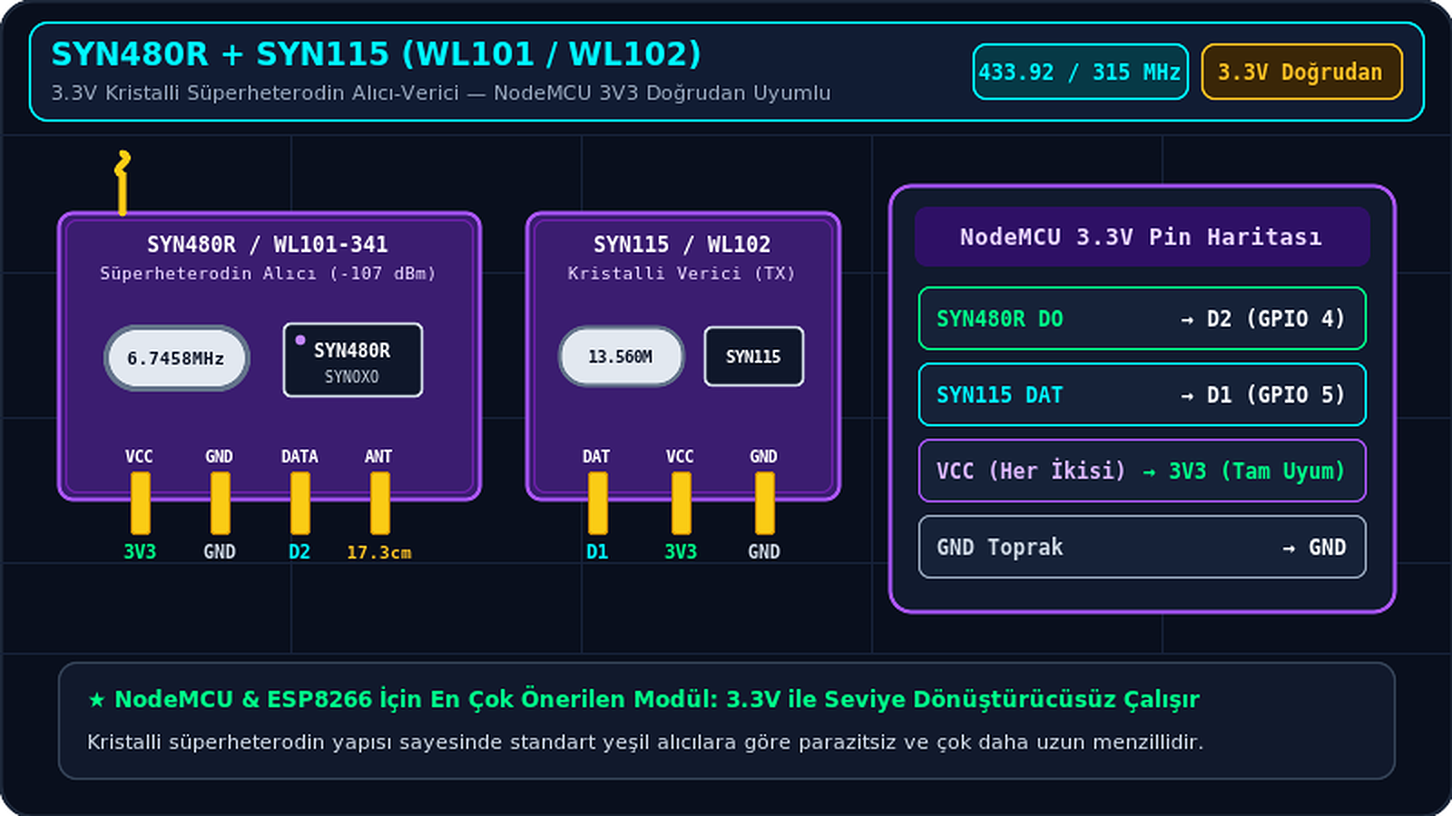
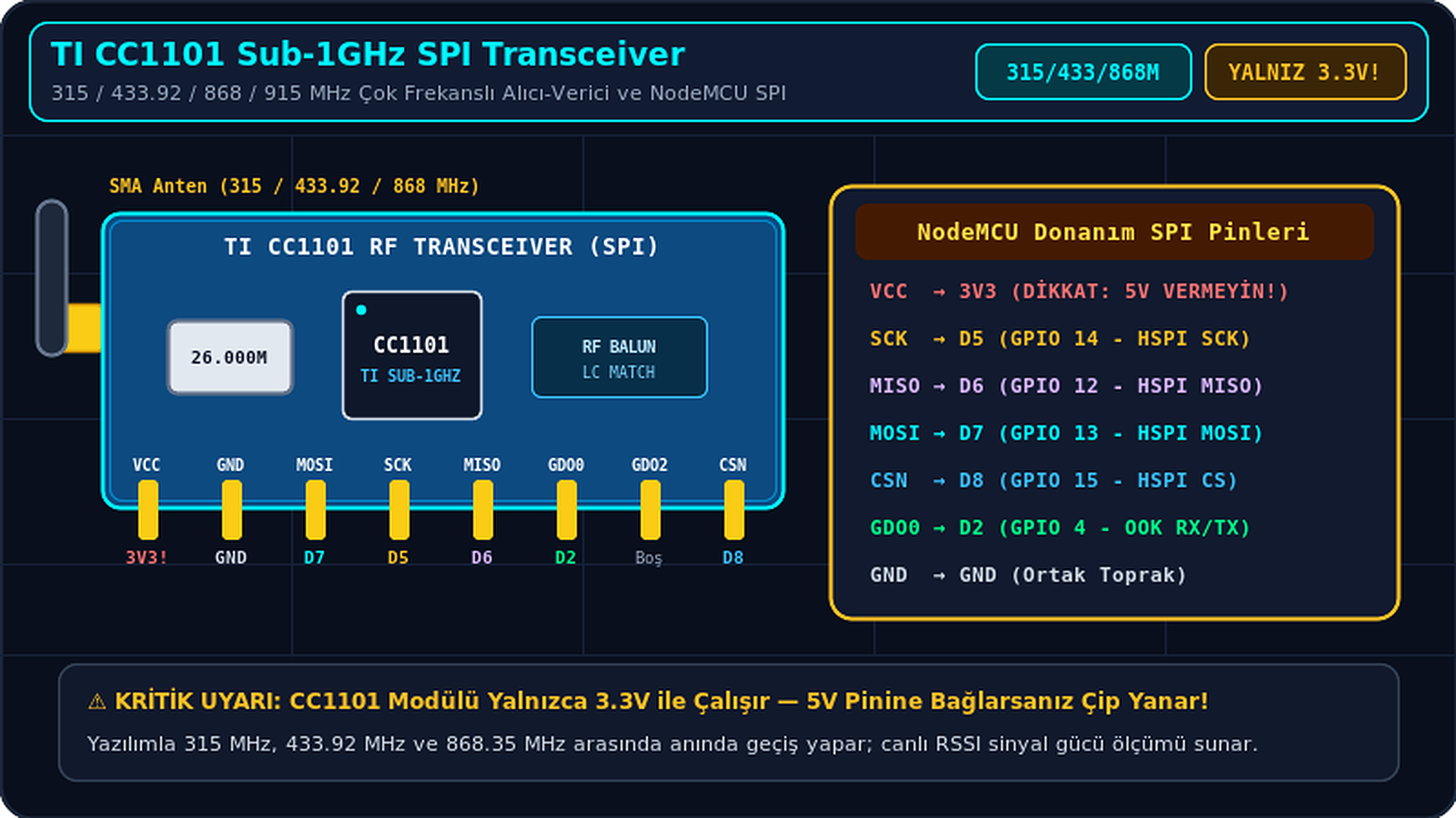
- 6 Ready Examples: (1) NodeMCU Wi-Fi Web Remote & 12-Slot EEPROM Cloner, (2) 24/28/32-Bit Fixed-Code Remote Cloner, (3) Raw Pulse Recorder & Replayer, (4) TI CC1101 SPI Multi-Band Transceiver & RSSI Scanner, (5) RX480E 4-Channel Remote Reader, (6) RF Signal Analyzer & ASCII Oscilloscope.
- Pre-compiled RF Firmware (Flash Directly Without Compiling): From the Hazır Derlenmiş RF Firmware card under Studio → RF & Remote or the Pre-built RF button under Flash, load the bundled pre-compiled
.binand.hexfirmwares for NodeMCU (ESP8266), ESP32 and Arduino Uno/Nano straight into the Flash tab with no internet or server compilation needed. The NodeMCU and ESP32 pre-built images start theADBnox_RF_KumandaWi-Fi AP (password:12345678, web UI:http://192.168.4.1). - Serial Terminal Commands (115200 baud):
STATUS/LIST(last received code and saved channels),CLONE:1:Garage(save the last received code to channel 1 under this name; channels 1–12),SEND:1(send a saved channel),TX:5592405:24:350(send a code given as a decimal number, bit count and pulse length in µs; without a pulse,TX:5592405:24uses the Manual send pulse),REPLAY(replay the last raw pulse recording),TXTEST(transmitter test, see below),CLEAR(erase saved channels). - Editing buttons and groups (1.4.0): The web remote's main screen shows only saved, active buttons. Under Edit buttons and learn remotes you record a new signal, rename a button, change its group or active state, or delete just that button (re-learn it to change the RF code). The last-code card shows the code read, its bit count and the measured pulse length; Send last code, Send raw pulses and Transmitter test are there. Buttons with the same group name appear under one heading; for example buttons 1–2 in
Building Aand 3–4 inBuilding B. Up to 12 buttons; names and groups up to 48 bytes. With EEPROM selected, they survive a restart. - Panel settings and optional password: The Panel settings section of the RF, Wi-Fi relay, sensor station and ESP32-CAM panels sets theme, AMOLED, palette and language, and can enable a web password (user
adbnox, 8–64 byte password; off by default). Local HTTP is not encrypted. If you forget the password, sendPANELRESETfrom the USB serial terminal; it removes only the password, not the RF buttons. ESP project flashing does not overwrite the board's erased NVS area, so existing buttons and password settings are kept. An APK update does not change the panel already running on a board; flash the current pre-built RF firmware or the recompiled project. - Reading and pulse length (1.5.3): On fixed-code remotes each bit is a HIGH and a LOW pulse, 3:1 for a 1 and 1:3 for a 0, so every bit is 4 pulses long. Cheap (superregenerative) receivers such as the XY-MK-5V stretch HIGH and shorten LOW; older versions measured the short pulses, so the saved length drifted by up to 20% with the code's mix of 1s and 0s and the copy might not match the receiver. 1.5.3 measures the pulse as a quarter of the bit length, requires every bit of a frame to share one timing and a 20–45 pulse sync gap after it. 3:1 codes of 24, 28 and 32 bits are decoded; other protocols such as HT6P20B and undecodable signals are captured as raw pulses while Raw Pulse Capture Mode (Ham Darbe (Raw Pulse) Yakalama Modu) is on (the default) and repeated with
REPLAYor Send raw pulses in the panel. Re-learn buttons copied with an older version after installing the current firmware; their saved pulse lengths keep the old measurement. - Sending: every transmission starts with a sync and sends the code as many times as the repeat count you chose (10 by default), so receivers that wait for a gap before data also take the first frame. The board's own receiver is switched off while sending, so the board does not copy its own signal.
- Manual send pulse (Elle Gönderim Darbesi) and Automatic (Otomatik) (1.5.4): every copied button is saved and sent with its own measured pulse; this field does not affect them. It is only for a code sent by hand without a pulse (
TX:<code>:<bits>). With Automatic (the default; the field shows empty) the last remote's measured pulse is used, or 350 µs before any signal is read. The preset buttons (EV1527 320 µs, PT2262 350 µs, HT6P20B 450 µs, Hızlı OOK 180 µs) or a number you type choose a fixed value. The pre-compiled RF firmware comes set to Automatic. - Transmitter test (1.5.3): tap Transmitter test in the web panel or type
TXTESTin the Serial Terminal. The board sends a fixed test code 4 times while its own receiver listens. The transmitter works means it radiates; the problem is range, pulse length or the target receiver. The receiver did not hear means checking the transmitter's antenna, 5V supply and DATA pin. The test changes neither the last captured code nor the saved buttons. A single CC1101 cannot send and listen at once, so it has no such test. - Copies but does not send: (1) solder a 17.3 cm antenna to the transmitter and power its VCC from VU (5V); (2) for the first try, bring the transmitter within 30–50 cm of the target receiver; (3) run the transmitter test; (4) re-learn the button with the current firmware; (5) check the bit count and pulse length in
STATUSand, if needed, try other pulse lengths (300–450 µs) withTX:<code>:24:350; (6) if the code changes on every press, the remote uses rolling codes and cannot be copied. - Which remotes can be copied: only fixed-code remotes (EV1527, PT2262 and similar). Most newer garage and car remotes change their code on every press (rolling code, such as KeeLoq); these cannot be copied, and a copied code does not work on the receiver. Use it only with your own remotes and devices.
- Choose the board and the template; fill in the pins, Wi-Fi details and intervals.
- Copy the generated code or share it as an
.inofile. - In the Sunucuda Derle ve Karta Yaz (compile on the server) card, enter your license code (
USB-…) once and tap Etkinleştir (activate). - Tap Derle ve Karta Yaz (compile and flash). The sketch is compiled on the ADBnox server (Uno about 1 s, ESP and Pico 3–10 s) and the file opens in the Flash tab with the right board type. Connect the board and write it with Program.
- If the sketch does not compile, the errors are listed under the card with their line numbers; fix the code and try again.
My projects: tap Kaydet (Save) in the Code Studio and give a name; the code is stored as a project. Open it from Projelerim (My projects) to keep editing and save the changes with Kaydet again; Farklı Kaydet (Save as) makes a copy. If there are unsaved changes when you open another template or project, the app asks first. Projects live in ADBnox/USB/Projects by default; each is a folder the Arduino IDE opens as is (Blink/Blink.ino plus its extra files). Sketch folders copied there from a computer show up in the list too. Change the folder in Settings → Projects Folder; existing projects move to the new folder. Seeing projects copied in from a computer needs All Files Access.
Compile history: every compile is listed with its result (success, code error, connection or server problem), date, total time (and the compile time on the server), board, program/RAM use and the first error line. The file of the last 30 successful compiles is kept: tap an entry to flash it again without compiling (Karta Yaz), save it to the phone as .hex / .bin / .uf2 (Dosyaya Kaydet) or bring that code back into the editor (Kodu Aç). The history keeps up to 100 entries.
Without a license code: copy the code or share it as an .ino file, compile it on a computer with the Arduino IDE (the required libraries are listed at the top of the code) PC, bring the .hex / .bin / .uf2 file to the phone and upload it with Flash.
About compiling on the server
- What is sent: only the code and the board type. The code is not stored; every compile runs in an isolated compiler without network access. Writing to the board always happens from the phone over USB.
- Internet is needed. The license is kept on the phone and renews itself every few days; compiling still needs a connection.
- Libraries are included by name:
#include <DHT.h>. Available: Servo, OneWire, DallasTemperature, DHT sensor library, Adafruit BME280, Adafruit MPU6050, Adafruit SSD1306, Adafruit GFX (plus Adafruit Unified Sensor and BusIO they need); LiquidCrystal (parallel LCD) on all but the ESP32 family; Keyboard and Mouse (USB keyboard/mouse) on Leonardo / Micro and Pico.#includelines with a file path are refused for security. - License term and compile allowance: a license can be unlimited, valid for a number of days or until a set date; some licenses also come with a number of compiles. What is left shows on the card as Kalan derleme hakkı (compiles left). Only a successful new compile uses one; compiles that end in a code error, come from the cache or fail on the server do not. When they run out, whoever issued the license can add more from the panel.
- Limits: up to 256 KB of code and an hourly compile limit. Compiling the same code again returns at once.
- Moving the license: before switching phones, tap Lisansı bu cihazdan kaldır (remove from this device) on the old one so the device slot is freed.
- Templates the board cannot run cannot be chosen. For example, templates that need Wi-Fi are disabled on Uno, Mega and Leonardo; Wi-Fi templates work on Pico W and Pico 2 W.
- Leonardo / Micro: the I2C pins differ from the Uno (SDA D2, SCL D3).
- ESP32-S3 / C3 and Pico 2: the LED pin comes as
LED_BUILTINand drives the board's own LED (the colour LED on S3/C3 DevKits). On boards with a plain LED such as the ESP32-C3 Super Mini, type8for the pin and turn on inverted logic. - Every supported board–template combination has been checked by compiling it with the real Arduino toolchain.
- To use the same sensors without compiling, choose IoT Agent instead of a template.
Sensors: ADBnox IoT Agent
IoT Agent is a single precompiled firmware for each board and comes inside the app. It is uploaded to the board once. After that, sensors and outputs are added from the phone, using the pin names printed on the board, and saved in the board's memory. No computer or code is needed.
Supported boards
Arduino Uno / Nano, old Nano, Mega 2560, Leonardo / Micro, ESP8266 (NodeMCU, D1 mini, ESP-01), ESP32, ESP32-S3, ESP32-C3, Raspberry Pi Pico / Pico W, Pico 2.
Supported sensors and outputs
| Type | Examples | Connection |
|---|---|---|
| Analog input | Soil moisture, LDR (light), MQ gas sensors, potentiometer | Analog pin (A0…) |
| Digital input | PIR motion, button, reed contact, IR obstacle | Any digital pin |
| Temperature / humidity | DHT11, DHT22 / AM2302, DS18B20, AHT10 / AHT20, SHT30 / SHT31 | One-wire or I2C |
| Pressure | BME280, BMP280 | I2C |
| Distance | HC-SR04 | TRIG + ECHO |
| Light | BH1750 | I2C |
| Motion | MPU6050 accelerometer + gyroscope | I2C |
| Current / voltage | INA219 | I2C |
| Weight | HX711 + load cell | DOUT + SCK |
| CO₂ | SCD40 / SCD41 (true CO₂ measurement, plus temperature and humidity) | I2C (0x62) |
| Soil moisture | Capacitive or resistive soil moisture sensor; shows a percentage after dry/wet calibration | Analog pin |
| Electricity use | PZEM-004T v3 (voltage, current, power, kWh, frequency, power factor) | RX + TX |
| Laser distance | VL53L0X (3–200 cm, in mm) | I2C (0x29) |
| Output | Relay, digital output (LED, active buzzer), PWM, servo | Digital / PWM pin |
| Colour LED | WS2812 / NeoPixel strip or ring (all LEDs the same colour) | Single pin |
| Buzzer | Passive buzzer at a chosen frequency | Single pin |
| Display | OLED 128×64 / 128×32 (SSD1306, SH1106), LCD 16×2 / 20×4 (with I2C backpack) | I2C |
Which drivers are on which board?
Because the Uno, Nano and Leonardo have little memory, some newer drivers are not available on them. The Add sensor dialog shows only the types available on the connected board.
| Board | Newer drivers | Number of rules |
|---|---|---|
| Uno / Nano | SCD40, soil moisture, WS2812, LCD (no PZEM, VL53L0X, buzzer or OLED) | 6 |
| Leonardo / Micro | No newer drivers; the earlier sensors and rules work | 6 |
| Mega 2560, ESP8266, ESP32, ESP32-S3, ESP32-C3, Pico, Pico 2 | All | 12 |
A board holds at most 10 sensors/outputs. One each of SCD40, PZEM, VL53L0X, OLED and LCD can be added per board.
- Upload the agent: in Programmer → Sensors choose your board; a connected board is recognised by its USB identity and preselected. Tap Load agent into the flasher: the Flash tab opens with the right target and file; write it with Program. Plug in a Pico while holding BOOTSEL.
- Connect: go back to the Sensors tab and tap Connect. The board reports the agent version and its I2C/analog pins. If the agent is old, the app offers to update it.
- Add sensors: with Add sensor choose the type and pins. You can type the pin name as printed on the board:
13,A0,D4(NodeMCU),GPIO21,GP15. The wiring diagram of each type appears in the dialog. - I2C scan: I2C scan lists the connected I2C devices with their addresses; tap a recognised device to add it with the right address.
- Save: Save to board writes the list to the board's EEPROM / flash. The board starts with the same sensors every time it powers up; it does not need to be connected to the phone.
- Watch: each sensor's current value and a chart of the last 240 readings are shown. Choose the reading interval between 250 ms and 10 s. With Record readings (CSV) on, incoming values are exported as CSV.
- Drive the outputs: switch the relay on/off; set PWM and the servo angle with a slider. Choose the colour of an LED strip and the tone of a buzzer; turn the display on and off.

Automation rules (working without the phone)
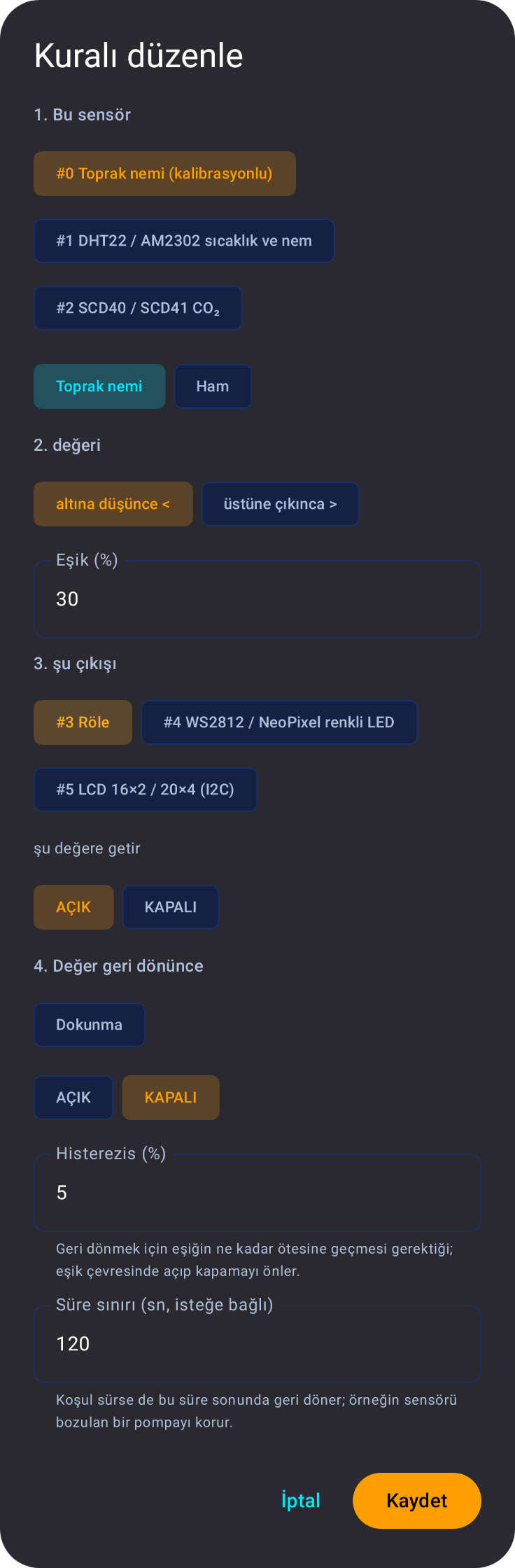
A rule is an “if … then …” relation that the board follows on its own. For example, “if soil moisture drops below 30%, switch the relay on; switch it off at 35%”. After saving with Save to board you can disconnect the phone; the board keeps following the rules every time it starts. Thermostats, watering, ventilation and alarms thus work without a phone or computer.
- Add at least one sensor and one output. On the Automation rules card tap Add rule.
- When this sensor: choose the sensor and, if it has several values, which value to watch (e.g. CO₂ on an SCD40).
- Value: choose “drops below” or “rises above” and enter the threshold.
- This output: choose the output and the value it takes: ON for a relay, a colour for an LED strip, a tone for a buzzer, an angle for a servo.
- When it comes back: choose the value the output returns to, or Leave as is.
- Hysteresis: how far past the threshold the value must go before returning. With a threshold of 30 and a hysteresis of 5, the relay switches on below 30% and off above 35%; it does not keep flipping around the threshold.
- Time limit (optional): even if the condition persists, the output returns after this time and the rule waits until the condition ends. It stops a pump with a broken sensor from running for hours.
- Tap Save, then Save to board in the toolbar.
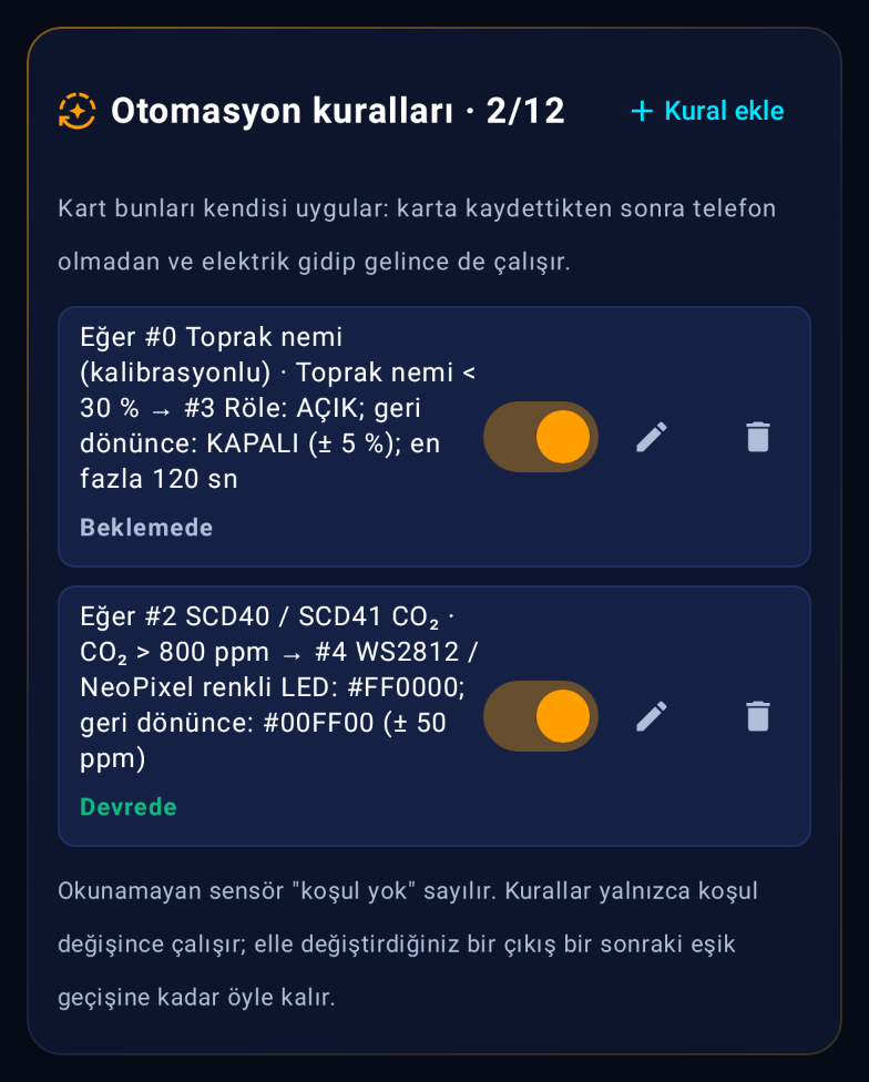
- A sensor that cannot be read (cable out, sensor broken) counts as “no condition”; the output goes to its return value.
- Rules act only when the condition changes. A relay you switched on by hand stays as you left it until the next threshold crossing.
- Deleting a sensor also deletes the rules that use it; if the remaining sensors are renumbered, the rules are updated with them.
- You can turn a rule off temporarily with its switch without deleting it.
Soil moisture calibration
The raw value of soil moisture sensors differs from sensor to sensor. To show a percentage, record two points:
- Hold the sensor in dry air and tap Dry (now).
- Dip the sensor up to its marked line in a glass of water and tap Wet (now).
- Tap Save to board. Before calibration the percentage is empty and the raw value is filled in.
On-board display (OLED / LCD)
When you add an OLED or LCD, the board shows the readings on it, one value per line; what does not fit turns page by page every 3 seconds. The switch on the display card turns the display off and on. If no text appears on an LCD, turn the blue contrast trimmer on the back; the address is usually 0x27 or 0x3F (I2C scan shows it).
PZEM-004T energy meter
Connect PZEM's TX to the pin you chose as the board's RX, and its RX to the TX pin. The energy (kWh) counter is kept inside the module; Reset the energy counter (kWh) resets it.
PZEM's L/N terminals and the current transformer are connected to the 230 V line. Only someone who knows electrical wiring should make this connection, with the circuit breaker off. Use the board and the module in a closed box.
HX711 scale calibration
- With the pan empty, tap Tare.
- Put down an object of known weight (e.g. 500 g), enter its grams and tap Calibrate.
- Values are now shown in grams; the calibration is kept with Save to board.
Wi-Fi web panel (ESP8266, ESP32, ESP32-S3, ESP32-C3)
ESP boards can show sensor values without the phone, too.
- On the Wi-Fi web panel card in the Sensors tab, enter your 2.4 GHz network's name and password and tap Join network. Or open the board's own
ADBnox-XXXXnetwork with Open own network. - The board reports its IP address. Open
http://<IP>/orhttp://adbnox-xxxx.local/in any browser on the same network. - The user name is
adbnoxand the password is the key shown on the card. This key is also the password of the board's own network. - The panel shows live values and charts; relays, PWM and servos can be used from here too. No internet is needed.
- Values can be read as JSON from
/api(home automation, your own scripts). Outputs are driven with/api/out?i=<index>&v=<value>. Both require the same user name and password. - Board with its own network (Agent 1.10.1): when a phone or computer joins the
ADBnox-XXXXnetwork, the system's “sign in to network” page opens the panel by itself; if it does not, openhttp://192.168.4.1/. In this mode the board answers every domain name itself and there is no internet./apiaddresses are not redirected. - New password invalidates the old password immediately. The settings are kept on the board; after a power cut the board reconnects.
- The panel shows the newer sensors too; the LED strip's colour is set with a colour picker and the buzzer's tone with a slider.
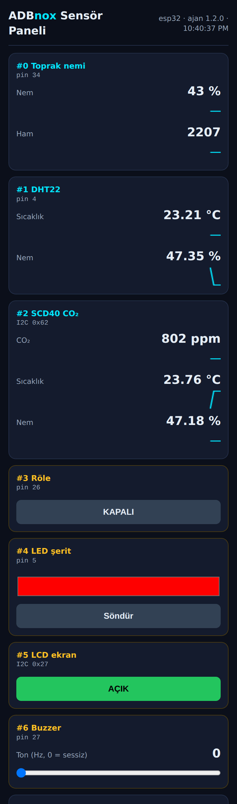
IoT cloud panel and advanced analysis
Create a device and enter its write key only in your own board’s Cloud / Webhook settings. Use https://iot.adbnox.com/v1/ingest and start with a 60-second interval. Select a metric in IoT web or Android to set the time range, zoom and export CSV. Visualizations save line, area, dual axes, step, scatter, histogram and X/Y correlation charts. IoT 0.8 single-metric analysis adds box plot, cumulative distribution, rate and spread. Boxes use raw quartiles; cumulative charts approximate percentages from histogram bins; rate uses differences of bucket means per hour; spread is each bucket’s maximum minus minimum. Outliers use 1.5×IQR. Trend is not a forecast, and an outlier is not evidence of a fault. New analysis needs the matching server update; check the displayed version. The cloud MQTT TLS development profile is not bundled in the released Agent.
File folders
The shared root in phone storage is ADBnox/USB: downloads use Downloads and projects use Projects. Choose each separately in Settings; custom selections are kept. Default paths use the new root directly; previous default folders are not scanned or moved automatically. Check the actual path in Settings. Without storage permission, projects use the app’s own storage.
General inputs: choosing and wiring a module
General inputs: AIN reads a changing voltage from an LDR, potentiometer, MQ gas AO or water-level module as raw ADC and mV. Lux, ppm and percent need sensor-specific calibration. DIN only reads 0/1: button, reed door contact, PIR motion, IR obstacle, flame/sound module DO. Select the dedicated type for I2C / 1-Wire sensors; these are not AIN/DIN.
HC-SR501: Add sensor → Digital input; OUT → unused digital pin, VCC → 5V, GND → GND, internal pull-up off. NodeMCU example: OUT → D5 (GPIO14), provided no other sensor uses it. Wait 30–60 s after power-on: 1 means motion, 0 means idle. The delay pot controls HIGH hold time; the H/L jumper selects repeat/single trigger. Follow the module pin labels.
Button/reed: one contact to the digital pin and the other to GND; enable internal pull-up. Released/open is 1, pressed/closed is 0. IR obstacle, flame and sound modules may be active LOW or HIGH; check your module before choosing an automation threshold. Use Counter rather than DIN to count pulses; slow sampling can miss short motion events.
Input limits: share GND and do not trust a floating pin. Analog voltage must stay within the ADC limit; a bare ESP8266 ADC is 1V, so check the divider on your NodeMCU. Never feed 5V to a 3.3V digital pin or connect a relay, motor or mains directly to an input.
The Displays card adds OLED/LCD modules and selects row sources, including calculated dew point from temperature/humidity. Notification details, Refresh and Panel buttons are configured separately in Settings; a Wi-Fi session can continue in the app after USB is removed.
MQTT and Home Assistant (ESP boards)
ESP boards can send readings to an MQTT server (e.g. Home Assistant's Mosquitto add-on). If the MQTT integration is enabled in Home Assistant, the sensors are listed automatically under a device called “ADBnox xxxx” (xxxx is the end of the board's name in the web panel); relays and displays appear as switches, PWM/servo/buzzer as numbers and the LED strip as a light, and they can be controlled from there too.
- First connect the board to your home network from the Wi-Fi web panel card.
- On the MQTT · Home Assistant card enter the server's address (e.g.
192.168.1.10), the port (1883) and, if any, the user name and password. Every is how often, in seconds, values are sent. - Tap Connect. When the state is Connected, you will see the board in Home Assistant under Settings → Devices & services → MQTT.
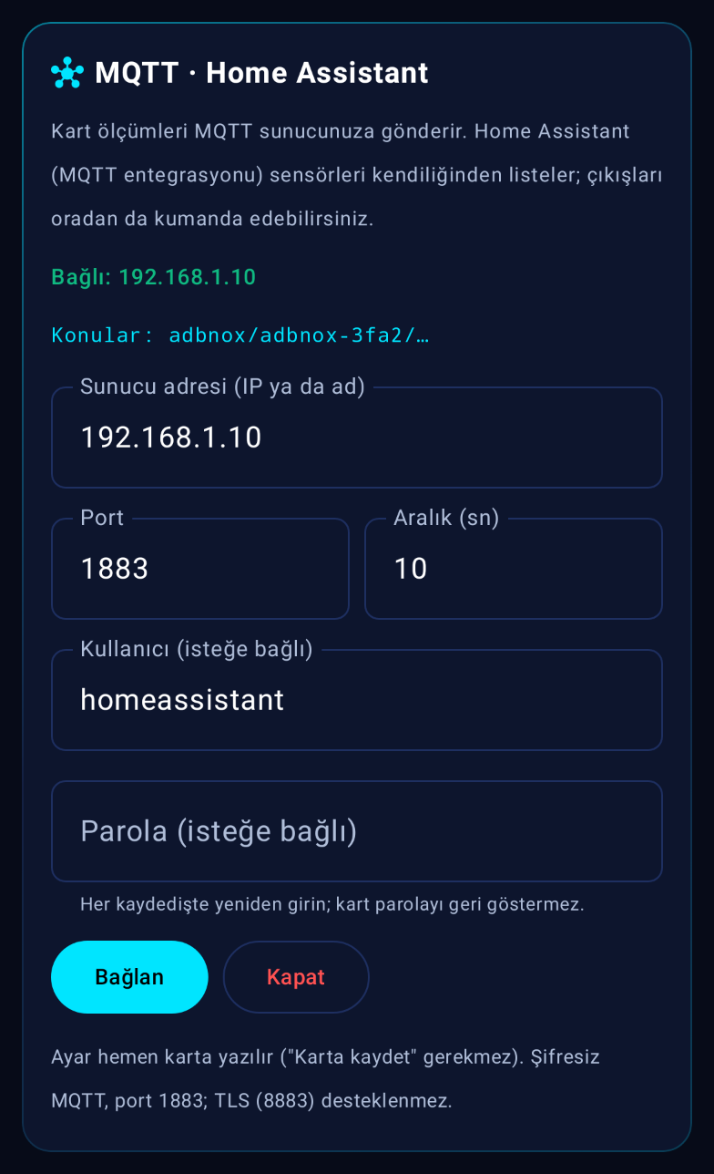
adbnox/adbnox-xxxx/… topics.- The setting is written to the board immediately; after a power cut the board reconnects to the server. The password is stored on the board but never shown again: enter it again when you change the setting.
- Only unencrypted MQTT (usually port 1883) is supported; TLS (8883) is not. Keep the server on your home network.
- Close stops sending. On an error the board states the reason: wrong password, server unreachable, no Wi-Fi and so on.
Connecting over Bluetooth (ESP32, ESP32-S3, ESP32-C3)
From agent 1.3 on, ESP32-family boards also talk over Bluetooth LE. Once the board has been set up over USB, you can connect the phone without a cable and do everything from there: join a Wi-Fi network, add sensors and rules, read values, drive outputs, update.
- Upload agent 1.3 once over USB. On the ESP32 family this first upload also changes the board's memory layout (two agent slots); the sensor list, rules and Wi-Fi settings are kept.
- While connected over USB, see the 6-digit PIN on the Bluetooth card (Show). Every board has its own PIN, chosen at random on first start.
- At the top of the connection card choose Bluetooth. The first time, the app asks for the Bluetooth permission (Allow Bluetooth). Tap Find boards; the board appears as
ADBnox-XXXX(the same name as its Wi-Fi access point). - Tap Connect. Android opens its own pairing dialog and asks for the PIN; type it. Later connections do not ask again.
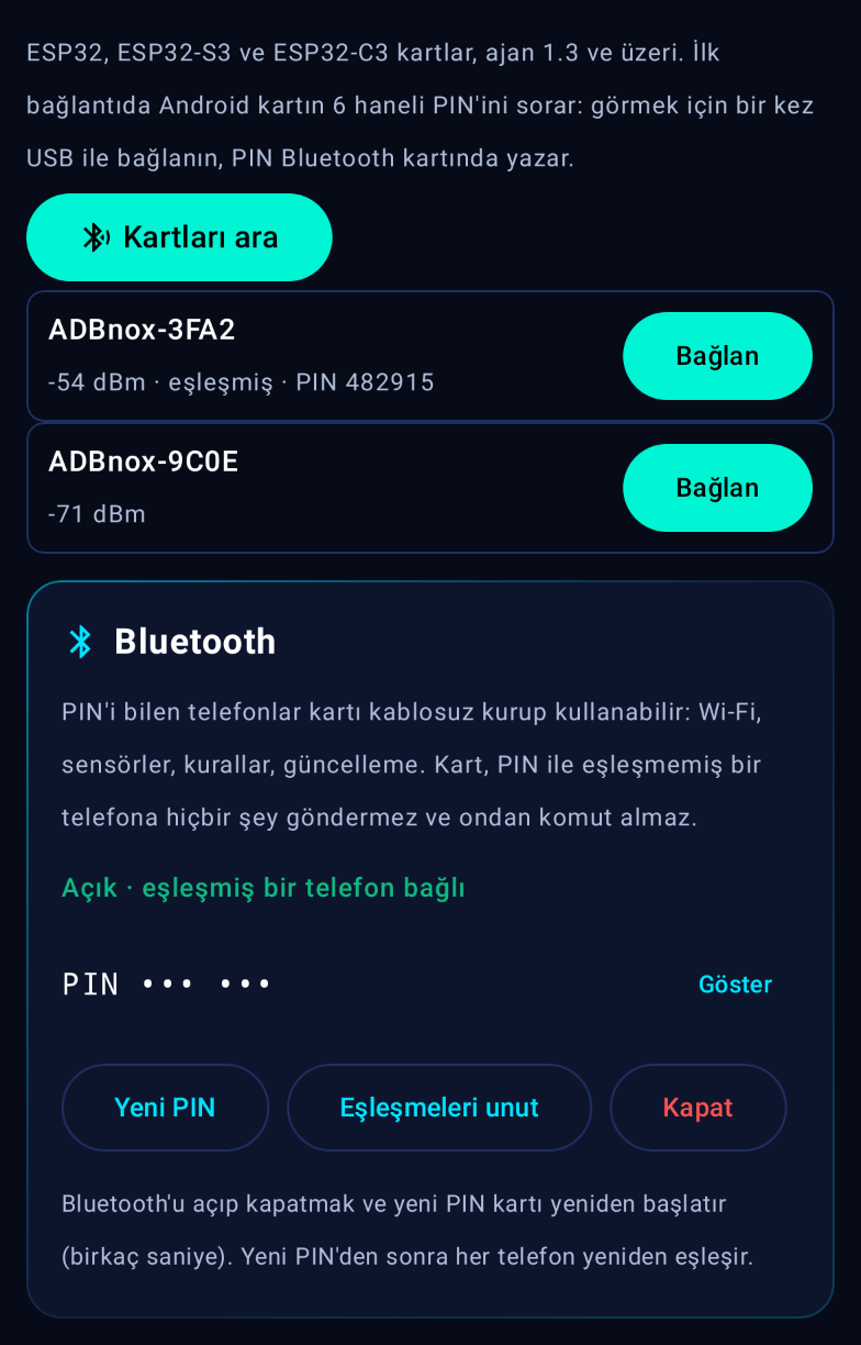
- The board sends nothing to, and takes no commands from, a phone that has not paired with the PIN. The link is encrypted (LE Secure Connections).
- New PIN restarts the board and clears old pairings; every phone pairs again with the new PIN. Forget paired phones keeps the PIN. Turn off switches Bluetooth off completely (also with a restart).
- If the app says “The board no longer knows this phone”, remove the phone's old pairing with Remove old pairing and connect again.
- Bluetooth works near the board (a few metres). ESP8266, Arduino Uno/Nano/Mega/Leonardo and the Raspberry Pi Pico have no Bluetooth.
- Bluetooth makes the agent bigger: on the ESP32 it uses about 93% of the agent slot in the new memory layout, on the S3 and C3 65–73%.
OLED / LCD content selection
Open IoT → Displays (OLED / LCD) and add your display. After its settings are read, choose Edit content. Select My four rows to assign a sensor reading, static text or blank to each row, then Send to board. Sources include sensor models and wiring. Custom content requires an ESP board and Agent 1.8.3+.
1.2.6 interface: The Device Programming home card lists Android Fastboot, Samsung Odin, boards, sensors, RF and IoT tools. Feature labels scroll horizontally. Serial Monitor follows Device Programming. RF details and fullscreen controls respect Android system bars. Downloads, writing and IoT notifications share a monochrome USB trident icon.
USB 1.2.6 and Agent 1.8.3
Install Agent once, then select supported sensors and modules from the list without compiling again for each wiring change. New drivers cover SHT4x, Si7021 and ADS1115. RF433TX lists FS1000A/SYN115; RF433RX lists XY-MK-5V/RXB6. Available drivers depend on board capacity; RF reception/transmission supports fixed-code protocols.
RF / IR Remotes: see RF / IR remote library.
On ESP boards, the OLED/LCD editor offers four rows of readings, static ASCII text or blanks and a 2–60 second page interval. Settings persist on the board and can be managed from USB, the local panel or IoT web/Android. Temperature and humidity produce dew point and temperature–dew point spread.
A notification keeps the Wi-Fi session running in the background with reconnection attempts after an outage. Control commands with uncertain delivery are never replayed automatically. Disconnect from the app or its notification. New modules still require physical verification on your board.
RF / IR remote library (USB 1.5.3, Agent 1.10.1)
For copying remotes and sending them from the phone without writing code. The library is stored on the phone; the board only receives and transmits.
- Add the modules: with Add sensor, add
RF433RX(XY-MK-5V / RXB6 receiver, DATA pin) andRF433TX(FS1000A / SYN115 transmitter, DATA pin); for IR,IRRXandIRTX. Example on NodeMCU: receiver D2, transmitter D1. Power the transmitter's VCC from VU (5V) and solder a 17.3 cm antenna to both modules. Feed a 5V receiver's DATA output to a 3.3 V board through a voltage divider. Tap Save to board. - Capture: hold the remote near the receiver and press a button. The receiver's line shows the code (e.g.
0x55A101) and the measured pulse length (e.g.350 µs). For IR, the NEC address and command are combined into one code. - Save: tap Save captured code and give the button a name (e.g. Open garage), a group (e.g. Home) and what it does. Buttons of the same group are listed under one heading. You can also correct the code and pulse length here; Add RF button manually adds a button whose code you know without copying it.
- Send: pick the transmitter under Transmit through and tap the button. A tap sends the code once (the board sends 10 repeats). Hold the button and it keeps sending until you let go: the next send goes out each time the board has finished the previous one and answered. Shutters and some garage doors move only while the remote is held.
- Read the result: Sent by board means the board carried out the command. When the board also has an RF receiver, Agent 1.10+ listens with it while sending: Sent; the board's receiver heard it means the transmitter radiates; the board's receiver did not hear it points at the antenna, the 5V supply or the DATA wiring. Neither confirms that the target device acted.
- Back up: Back up to a file saves the library as a JSON file where you choose; Add from a file adds buttons from another phone or a backup (the same buttons are not added twice). The codes can open doors and gates, so do not share the backup file; for the same reason the app never copies codes to the clipboard.
- Pulse length: Agent 1.10 and later send each RF button with its own measured pulse length (the
RFTXcommand), so remotes with different timings can share one transmitter. An older Agent uses the single pulse length entered when the transmitter was added; update the board for buttons with other lengths. - Supported codes: 24-bit 3:1 fixed codes on RF (EV1527, PT2262 and similar) and NEC on IR. The Agent has no raw pulse recording; for protocols such as HT6P20B use the RF Remote Cloner in Project & Code. Rolling-code remotes show no code or a different one on every press; they cannot be copied.
- Clear receivers: deletes the last captured code (
RFCLR); use it before teaching a new button. The board's own transmission never shows up as a captured code. - Limits: up to 200 buttons in the library; names and groups 64 characters, descriptions 160. The code appears as a decimal number in the board's data line.
- Automation: rules can use an RF transmitter as their output; a rule sends with the pulse length entered when the transmitter was added.
Signed updates across networks
The current version in the app is ADBnox IoT Agent 1.10.1 (ADBnox USB 1.5.8). Remote updates need at least Agent 1.8.3 on the board, installed first over USB, local Wi-Fi or Bluetooth. Future signed releases can be queued from the device page at iot.adbnox.com. On its next report, the board downloads the package from the same HTTPS server, checks its signature, model, version and SHA-256, then restarts. Completion requires a report from the target version. Requests expire after 24 hours; cancellation cannot stop an installation already underway.
Readings and automation may pause during installation and outputs return to startup values. ESP8266 support is experimental and requires physical testing; memory or TLS limits can prevent downloading. Keep power connected; USB recovery may be required.
Wireless update (ESP8266, ESP32, ESP32-S3, ESP32-C3)
From agent 1.3 on, boards take new agent versions without a cable. When the agent inside the app is newer than the one on the board, the connection card says so (“A newer agent is ready.”).
- Over Wi-Fi: first connect the board to a network from the Wi-Fi web panel card, with the phone on the same network (or join the board's own network). On the Wireless update card tap Update over Wi-Fi. It takes a few seconds.
- Over Bluetooth: while connected over Bluetooth, tap Update over Bluetooth. On an ESP32 it takes one to three minutes; a progress bar is shown. Cancel drops the update and the old agent keeps running.
- From a computer: save the package with Save package (.adbfw). Open the board's web panel, choose the file in the ADBnox IoT Agent güncelleme (agent update) section at the bottom and press Karta yükle (upload to board). The panel is in Turkish.
- The board restarts (a few seconds). Connected over USB or Bluetooth, the app reads the agent again; over Bluetooth it reconnects by itself.
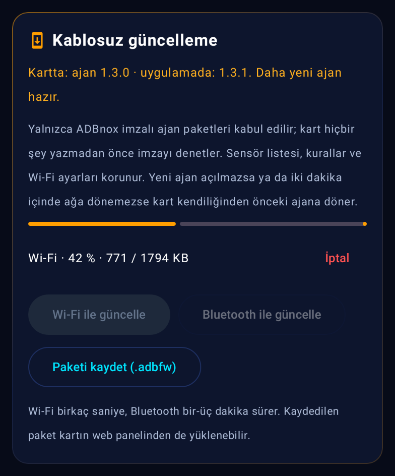
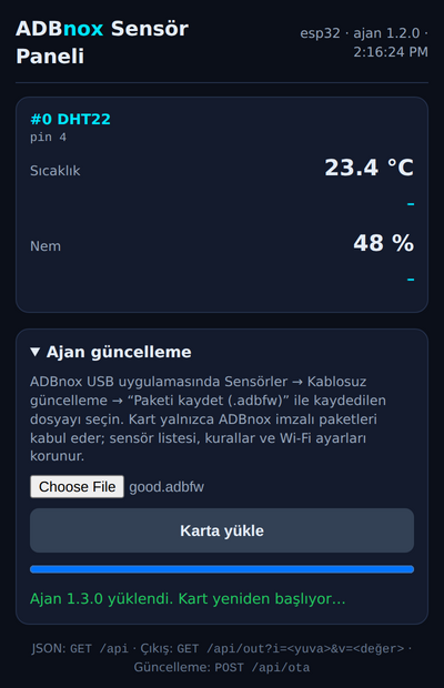
- Signature: the board accepts only agent packages signed by ADBnox. Before it writes anything it checks the signature, which board the package is for and the version; it refuses older versions, packages for another board and damaged files. The app runs the same checks before sending.
- Safety net (ESP32, S3, C3): the new agent is written next to the old one. If the new agent does not start, or does not get back onto its configured Wi-Fi network within two minutes, the board returns to the previous agent by itself. The ESP8266 has no such safety net: if the new agent does not start, upload it over USB.
- The sensor list, rules, Wi-Fi, MQTT and Bluetooth settings are kept across updates.
- An update over Wi-Fi uses the board's panel password. Share the password and the Bluetooth PIN only with people you trust.
- Arduino Uno/Nano/Mega/Leonardo and the Pico have no wireless link; they are updated over USB.
Problems
- The board does not respond: it runs another program; upload the agent. From the Agent console you can also send commands such as
LIST,SCAN,ADD DHT22 2by hand. - 3.3 V boards (ESP, Pico): connect sensors with 5 V outputs (e.g. the ECHO pin of an HC-SR04) through a voltage divider; otherwise the board's pin can be damaged.
- An I2C device does not show up: check that SDA/SCL are on the right pins, that the sensor is powered and that the module has pull-up resistors.
- No RF code shows up: check the receiver's DATA pin and 5V supply, bring the remote closer, tap Clear receivers and try again. If no code ever appears, the remote uses an unsupported protocol or rolling codes.
- An RF button is sent but the device does not react: fit a 17.3 cm antenna to the transmitter, power it from VU (5V) and move it closer to the target. If the result says the board's receiver did not hear it, the problem is on the transmitter side. Capture the button again with Agent 1.10.1: older versions could mismeasure the pulse length on XY-MK-5V receivers.
- The rules card does not appear: the board has an old agent (1.1 or earlier). Update the agent; the sensor list is kept.
- A type is missing in Add sensor: that driver is not on this board (see the table). Use a bigger board (Mega, ESP32, Pico).
- SCD40 empty for the first minutes: the sensor gives its first reading after 5 seconds; values settle within a few minutes.
- The board is not found over Bluetooth: it needs agent 1.3 or newer with Bluetooth on (Bluetooth card). The phone's Bluetooth must be on; on Android 11 and earlier, location too.
- “Update over Wi-Fi” is greyed out: the board is not on a network yet. Connect it from the Wi-Fi web panel card first.
- “Could not reach the board over Wi-Fi”: the phone is not on the board's network. When connected to a board's own network, if Android says the network has no internet access, choose to stay connected.
- “does not fit: install once over USB”: the board still has the memory layout from before 1.3. Upload the agent once over USB; later updates are wireless.
11 Serial Monitor
Talks to Arduino, ESP, modems and USB-serial adapters; draws incoming numbers as a live chart.
- Supported chips: CDC ACM (Arduino Uno R3/R4, Leonardo, Pico, native USB of ESP32-S3/C3), FTDI FT232, Silicon Labs CP210x, WCH CH340 / CH341.
- Baud rate: chosen from a list from 300 to 921600 baud, 74880 included; 8 data bits, no parity, 1 stop bit (8N1). It must match the speed in the board's code.
- View: incoming data as text (ASCII) or hexadecimal (HEX). You can choose the characters added to the end of a sent line (LF, CR, CRLF or none).
- DTR / RTS: switch them on and off by hand to reset a board or for flow control.
- Live plotter: if the board sends one number per line (
Serial.println(analogRead(A0));), the values are drawn as a chart. The current, minimum and maximum values and the number of points are shown. - Find speed: the app listens one and a half seconds each at 115200, 74880, 9600, 57600, 38400, 19200, 230400, 460800 and 921600 baud and picks the rate with the most readable text. The log shows how many bytes came at each rate and how much of it was readable. The board must print something meanwhile: press its RST button once the search starts.
- Loopback test: checks that what the phone sends leaves the adapter's TX pin. Join the TX and RX pins with a wire and keep the board quiet (on a NodeMCU, DTR off and RTS on holds it in reset; or hold RST; a separate module can simply be unplugged from the board). The app sends a short text and says whether it came back.
- Log: the buttons at the top right copy it, save it as a
.txtfile or share it.
The baud rate differs from the board's code. An ESP8266 prints its boot message at 74880 baud and its program usually at 115200, so both can show on one screen. When most incoming data is unreadable the app says so once; Find speed searches for the right rate.
The board restarts for lack of power. Power it from 5V with a short, sound cable. The app warns when it sees this line.
12 History and Settings
History
Every image write and disk operation on this phone is recorded: date, drive, operation, duration, speed, verification result (e.g. “Full verification passed”) and error details. Entries can be filtered by category. The log can be exported as text; send it when asking for support. Clear History cannot be undone; export first if needed.
Settings
| Setting | What it does |
|---|---|
| App Language | Turkish, English or the system language. |
| Appearance & Theme | System, dark, light; AMOLED pure black for OLED screens. |
| Destructive Action Guard (Strict Guard) | Identity and capacity check before every format and write. Keep it on. |
| Automatic Post-Write Verification | SHA-256 read-back verification when writing finishes. |
| Keep Screen On During Operations | Stops the screen and USB power from turning off during long jobs. |
| Floating Progress Panel and its aspect ratio | A progress window when you switch to another app; 16:9, 4:3, 21:9. |
| USB Transfer Buffer Size | The data moved in one USB command. A large buffer is faster on USB 3; make it smaller if the connection drops. |
| In-App Notification Duration | How long notifications stay on screen, or permanently. Holding a notification pauses it, and its text can be copied. |
| Download & Save Directory | The folder where ISOs, image backups and reports are saved (e.g. an SD card). |
| All Files Access Permission | Android's extended file permission, for writing directly to the ADBnox/USB/Downloads folder and for large .img dumps. |
13 Troubleshooting
Nothing appears when the drive is plugged in
- Turn on the phone's OTG setting (see Requirements).
- Try another adapter. Some cheap adapters are for charging only.
- Try the drive on a computer; if it does not appear there either, the drive is faulty.
- Use a hub with external power for external disks.
A write or test stopped half-way with “CSW transfer failed”, “CSW read timed out” or “MEDIUM NOT PRESENT”
The drive stopped answering commands or lost its storage for a moment; usually because of power, heat or a cheap controller. The app first resets the drive and retries with smaller chunks; for “MEDIUM NOT PRESENT” it also tries restarting the drive once (START UNIT). If that does not help, the error box says what happened and what to do; the raw error text is under Technical detail. After such an error, unplug the drive and plug it in again. If it keeps happening:
- Keep the screen on and take the phone out of power-saving mode.
- Try another OTG adapter; a loose or weak adapter can cut the drive's power.
- Make the USB Transfer Buffer Size smaller in Settings.
- Plug the drive in directly (without an extension cable or hub).
- If the problem repeats at the same point, run the fake-capacity test.
“Another operation is using the USB device”
A write, format or programming job is running in the background. Check its state in the notification; wait for it to finish or cancel it.
“Hardware identity verification failed”
After you confirmed, the drive was removed, another drive was plugged in or the connection dropped for a moment. Plug the drive in again and start the operation from the beginning.
“Medium is write-protected”
The lock switch on the side of the SD card adapter is in the “Lock” position, the drive has an ADBnox write lock, or the drive has reached the end of its life and made itself read-only (some flash controllers do this).
The ISO I downloaded does not appear in the file picker
Choose Downloads or the phone's name in the file picker's side menu. Files downloaded with ADBnox also appear in the Downloads list on Flash Image.
Uploading to an Arduino says “not in sync / no sync”
- Make sure you chose the right board model. On Nano clones try the “old Nano” option.
- Close the Serial Monitor if it is open; the port can be used by only one place at a time.
- Check on the Devices screen that the board's USB-serial chip (CH340, CP2102…) is supported.
Uploading to an ESP says “No sync”
- Read the Hint line in the log; it names the likely cause.
- No boot output after the automatic reset means DTR/RTS do not reach the board's EN and IO0 pins (a separate USB-serial module, ESP32-CAM). Choose Manual (BOOT), wire IO0 to GND and press RST.
- “The chip started its own program” means IO0 was not low at reset: keep BOOT held until the reset is over.
- If the board is in download mode but does not answer, check the phone-to-board direction with the Loopback test in the Serial Monitor, and that the module's TX goes to the board's RX.
- Disconnect the Serial Monitor if it is open; the port can be used by only one section at a time. The app names the section that holds it.
14 Frequently asked questions
Is root needed?
No. Only the virtual drive tool needs root.
Is internet needed?
Writing, formatting, tests and programming work completely offline. Internet is needed only to download images from the rescue library and to install apps after a Windows installation.
Does the app send my data anywhere?
No. The app contains no telemetry or ads. Reports and logs leave the phone only if you share them.
Can I write an image to the phone's own SD card?
No. Android does not give apps raw access to the card in the phone's SD slot. Connect the card with a USB card reader.
Does it work with an external HDD/SSD?
Yes, with enclosures that use USB mass storage (BOT). Some enclosures that speak only the UAS protocol may not appear on the phone. Use external power.
Can I format NTFS?
Not yet. NTFS drives are recognised and read; formatting is done with FAT32 and exFAT.
Can I prepare a Windows drive for an old (BIOS) computer?
No. The Windows drive boots only with UEFI. Almost every computer made after 2012 is UEFI.
15 Glossary
- OTG
- On-The-Go: the phone's ability to act as a host for USB devices.
- VID:PID
- A USB device's vendor and product identity (e.g. 0781:5581).
- LBA
- Logical block address: the number of a sector on the disk, starting from 0.
- Sector
- The smallest unit read from or written to a disk; 512 bytes on USB drives.
- MBR
- The old partition table; in the first sector of the disk, at most 4 primary partitions, 2 TB limit.
- GPT
- The new partition table; 128 partitions, very large disks, a backup copy at the end of the disk.
- PBR
- Partition boot record: the first sector(s) of a partition.
- FAT32
- The most compatible file system; a single file can be at most 4 GiB.
- exFAT
- A FAT-family file system for large files.
- NTFS
- Windows's main file system.
- UEFI
- The modern computer firmware that replaced the BIOS.
- CSM / Legacy
- UEFI's mode of behaving like an old BIOS.
- Secure Boot
- A UEFI feature that lets only signed boot loaders run.
- ESP
- EFI system partition: the FAT32 partition that holds UEFI boot loaders.
- TPM
- Trusted Platform Module; the security chip Windows 11 asks for.
- WIM / ESD / SWM
- Windows image files; SWM is a part of a split WIM.
- ISO
- The CD/DVD image format; operating systems are distributed in it.
- Hybrid ISO
- An ISO with a partition table at the start that boots when written to USB as-is.
- OOBE
- Windows's first-start setup screens (account, privacy…).
- DFU
- USB Device Firmware Upgrade: the mode in which chips such as STM32 are written over USB.
- UF2
- The drag-and-drop firmware format of boards such as the Pico.
- I2C
- A two-wire (SDA, SCL) bus for sensors; each device has an address.
- iPXE
- An open-source boot loader that starts a computer from the network.
16 Licences and notices
ADBnox USB's disk, file system and image engines were written from scratch, based on published specifications. Third-party components shipped with the app and their licences:
- GNU GRUB 2.12 (GPL-3.0+): the ADBnox MultiBoot boot loader, written to the drive. Built unmodified; source: Ubuntu
grub2package 2.12-1ubuntu7.3 (launchpad.net/ubuntu/+source/grub2). - iPXE (GPL-2.0+): network boot, written to the drive. Unmodified source, commit
8865571f(github.com/ipxe/ipxe). The fileadbnox_multiboot/IPXE-SOURCE.txton the drive carries this information. - DejaVu Sans font (free licence): the MultiBoot menu.
- Arduino cores (AVR, ESP8266, ESP32, arduino-pico; LGPL-2.1+), ESP-IDF (Apache 2.0) and the Pico SDK (BSD-3): the IoT Agent firmware written to boards.
- micro-ecc (BSD-2, Kenneth MacKay): the update signature check of the IoT Agent on ESP boards. On the ESP32 family, ESP-IDF's Bluetooth stacks (Bluedroid, NimBLE; Apache 2.0).
- Kotlin, kotlinx-coroutines, AndroidX, Jetpack Compose (Apache 2.0) and XZ for Java (0BSD): the app itself.
- The source code of GPL and LGPL components is also available on request.
The full list is in the app under Settings → About & Licenses → Open Source Licenses. Images in the rescue library are downloaded from their makers' official servers under their own licences.
Windows is a trademark of Microsoft Corporation; Raspberry Pi of Raspberry Pi Ltd; Arduino of Arduino SA. ADBnox USB is not affiliated with these companies.
ADBnox FW Agent — update your own project wirelessly
FW Agent uploads Arduino programs compiled in Studio over Wi-Fi or Bluetooth LE on supported boards. After the first USB installation, every FW build includes a small update component. The ready-made sensor and automation firmware, IoT Agent, is a separate option.
What you need
ADBnox USB 1.4.0+, at least 4 MB flash and OTG for first installation. NodeMCU V3 / WeMos D1 (ESP8266) and ESP32-S2 use Wi-Fi. ESP32, ESP32-S3, ESP32-C3, ESP32-C6 and ESP32-CAM support Wi-Fi and Bluetooth LE. Pico and AVR FW runtimes are not included. Installing the bundled bootstrap needs no license; compiling your own code needs a USB license and internet.
1 · Install once over USB
- Select your board in Programmer → Studio. Open the setup steps in the ADBnox FW Agent card.
- Select “Send FW Agent installer to Flash”. In Flash, select the correct USB device, grant access and confirm writing.
- This initial installation replaces the current program and board settings. When writing finishes, return to Studio with USB still connected.
2 · Pair (while USB is connected)
The four steps at the top (USB install → Pair → Connect → Upload) show where you are. If the installer is already on the board, choose “Already installed → Pair”; for a board you paired before, choose “Connect to my saved board”.
Close Serial Monitor and IoT connections. If no USB board is listed, check the OTG cable and choose “Allow USB access”. On Bluetooth-capable boards choose Wi-Fi + Bluetooth or Bluetooth only. For Wi-Fi, pick the board's 2.4 GHz network with Find networks or Saved networks, or type it in; a saved network fills its password. Choose “Pair the connected USB board”. This phone becomes the update owner; its private key stays on the phone. The app verifies the connection automatically after pairing.
3 · Connect
On Wi-Fi the phone must be on the board's network: use “Find FW boards on Wi-Fi”, select the board, then “Connect and verify board”. If it is not found, use “Edit address manually” and enter its IP or adbnox-fw-<device-id>.local, without http:// or a port. For Bluetooth, allow nearby-device access and use “Find Bluetooth devices”; BLE does not need Wi-Fi. Rename a saved board or remove it with Forget on this phone; a forgotten board must be paired over USB again. If the network or password changed, use “Configure network / pairing over USB”. Older Wi-Fi-only FW projects need a new FW build installed over Wi-Fi or USB first.
4 · Upload
- Edit your code and select “Compile with FW Agent support”. The update component is added automatically; the editor's original source stays unchanged.
- Check the prepared build's board and identity. Compile again after any further edits: a prepared build is a source snapshot.
- Select the Wi-Fi or Bluetooth upload action. Check the device identity in the confirmation. The board checks the signature, device, chip, flash layout and image.
- The board restarts after upload. Completion is shown only after the correct build is confirmed running. Keep power connected throughout.
Connection loss and saved builds
Use “Check the last upload outcome”. An update with an unknown outcome is not sent again automatically. Recent FW builds can be prepared from history without recompilation. Returning to older project code is a new signed deployment. Old ordinary USB builds have no FW OTA support.
How this differs from the IoT panel
| Option | Purpose | Update channel |
|---|---|---|
| IoT Agent | Ready-made sensors, outputs and automation | Agent update in the USB app, or an authorized remote Agent update in the IoT panel |
| FW Agent | Your own compiled program | USB app → Studio → FW Agent → local Wi-Fi or Bluetooth LE |
FW Agent alone sends no sensor telemetry. Configure project MQTT/webhook separately. When the MQTT template is built with FW support, the IoT panel recognizes a custom project and does not offer a ready-made IoT Agent release. This release does not distribute custom projects over the internet. Uploading a prepared build locally needs no IoT account or cloud service.
Recovery and supported project behaviour
Every new project must include FW support. Flashing ordinary USB firmware can remove both the update component and pairing settings. The FW history action prepares a Wi-Fi upload; it does not automatically send the image to ordinary USB flashing.
Your setup() and loop() functions must return and allow Wi-Fi and the FW task to run. A project web panel can use port 80; FW Agent uses port 3232. Up to 25 user source files are supported; ADBnoxFW*, FWPlatform.h, FWBle.h, fw_protocol.h and sha256.h are reserved.
ESP8266 has no automatic boot rollback and its loop must return regularly. The bootstrap prepares a 4 MB / 2 MB filesystem profile; owner records live there, so project code must not format it. ESP32-CAM uses two OTA slots of about 1.9 MB, and oversized camera projects must be reduced.
Automatic boot rollback depends on bootloader support and is reported when you verify the board. There is no separate resident recovery app in this release. If a project hangs or disables Wi-Fi, reinstalling the bootstrap over USB may be necessary. Also reinstall and pair after changing phones or clearing app data; this replaces the user project.
Use a trusted local network. Owner signatures and status authentication do not encrypt firmware contents. Verify physical board, GPIO and power-loss behaviour on your own hardware.